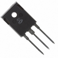
APT47N60BCFG Microsemi Power Products Group, APT47N60BCFG Datasheet - Page 2

APT47N60BCFG
Manufacturer Part Number
APT47N60BCFG
Description
MOSFET N-CH 600V 46A TO-247
Manufacturer
Microsemi Power Products Group
Series
CoolMOS™r
Datasheet
1.APT47N60BCFG.pdf
(5 pages)
Specifications of APT47N60BCFG
Fet Type
MOSFET N-Channel, Metal Oxide
Fet Feature
Standard
Rds On (max) @ Id, Vgs
83 mOhm @ 29A, 10V
Drain To Source Voltage (vdss)
600V
Current - Continuous Drain (id) @ 25° C
46A
Vgs(th) (max) @ Id
5V @ 2.9mA
Gate Charge (qg) @ Vgs
255nC @ 10V
Input Capacitance (ciss) @ Vds
7290pF @ 25V
Power - Max
417W
Mounting Type
Through Hole
Package / Case
TO-247
Lead Free Status / RoHS Status
Lead free / RoHS Compliant
DYNAMIC CHARACTERISTICS
SOURCE-DRAIN DIODE RATINGS AND CHARACTERISTICS
THERMAL CHARACTERISTICS
APT Reserves the right to change, without notice, the specifications and information contained herein.
1 Repetitive Rating: Pulse width limited by maximum junction
2 Repetitive avalanche causes additional power losses that can
3 Starting T
Symbol
Symbol
Symbol
temperature
be calculated as P
t
t
R
I
R
C
C
V
dv
C
Q
Q
d(on)
d(off)
E
E
E
E
I
Q
RRM
Q
SM
t
I
θJC
θJA
oss
t
t
SD
rss
iss
on
off
on
off
S
rr
gs
gd
/
r
f
g
rr
dt
0.35
0.30
0.25
0.20
0.15
0.10
0.05
j
0
= +25°C, L = 36.0mH, R
Characteristic
Junction to Case
Junction to Ambient
Characteristic
Input Capacitance
Output Capacitance
Reverse Transfer Capacitance
Total Gate Charge
Gate-Source Charge
Gate-Drain ("Miller ") Charge
Turn-on Delay Time
Rise Time
Turn-off Delay Time
Fall Time
Turn-on Switching Energy
Turn-off Switching Energy
Turn-on Switching Energy
Turn-off Switching Energy
Characteristic / Test Conditions
Continuous Source Current (Body Diode)
Pulsed Source Current
Diode Forward Voltage
Peak Diode Recovery
Reverse Recovery Time
(I
Reverse Recovery Charge
(I
Peak Recovery Current
(I
10
S
S
S
-5
= -46A,
= -46A,
= -46A,
FIGURE 1, MAXIMUM EFFECTIVE TRANSIENT THERMAL IMPEDANCE, JUNCTION-TO-CASE vs PULSE DURATION
D = 0.9
AV
0.7
0.5
0.3
0.1
0.05
= E
di
di
di
AR
/
/
/
dt
dt
dt
*f
= 100A/µs)
= 100A/µs)
= 100A/µs)
5
10
G
-4
dv
= 25Ω, Peak I
1
4
/
dt
(Body Diode)
(V
6
6
7
GS
= 0V, I
SINGLE PULSE
L
= 10A
RECTANGULAR PULSE DURATION (SECONDS)
S
10
= -46A)
-3
INDUCTIVE SWITCHING @ 125°C
INDUCTIVE SWITCHING @ 25°C
4 Pulse Test: Pulse width < 380 µs, Duty Cycle < 2%
5 See MIL-STD-750 Method 3471
6 Eon includes diode reverse recovery. See figures 18, 20.
7 Maximum 125°C diode commutation speed = di/dt 600A/µs
RESISTIVE SWITCHING
V
V
Test Conditions
DD
I
I
DD
D
D
I
I
D
D
= 46A, R
= 46A, R
= 400V, V
= 400V, V
V
V
= 46A @ 25°C
= 46A @ 25°C
V
V
V
R
f = 1 MHz
V
DD
DD
T
T
T
T
T
T
GS
DS
GS
G
GS
j
j
j
j
j
j
= 25°C
= 125°C
= 25°C
= 125°C
= 25°C
= 125°C
= 3.6Ω
= 380V
= 300V
= 25V
= 15V
= 10V
10
= 0V
G
G
-2
GS
GS
= 4.3Ω
= 4.3Ω
= 15V
= 15V
Note:
Peak T J = P DM x Z θJC + T C
MIN
MIN
MIN
10
Duty Factor D =
-1
t 1
APT47N60BCF_SCF(G)
7290
1735
1270
t 2
TYP
TYP
TYP
255
135
100
885
590
725
350
210
2.0
5.4
18
28
41
43
30
30
15
t 1
/
t 2
MAX
115
MAX
MAX
0.30
1.2
40
46
62
1.0
Amps
Amps
UNIT
UNIT
Volts
UNIT
°C/W
V/ns
µC
nC
pF
ns
µ
ns
J


