EMD29T2R Rohm Semiconductor, EMD29T2R Datasheet

TRANS COMPLEX DGTL PNP/NPN EMT6

EMD29T2R

Manufacturer Part Number
EMD29T2R
Description
TRANS COMPLEX DGTL PNP/NPN EMT6
Manufacturer
Rohm Semiconductor
Datasheet

Specifications of EMD29T2R

Transistor Type
1 NPN, 1 PNP - Pre-Biased (Dual)
Current - Collector (ic) (max)
100mA, 500mA
Voltage - Collector Emitter Breakdown (max)
50V, 12V
Resistor - Base (r1) (ohms)
1K, 10K
Resistor - Emitter Base (r2) (ohms)
10K
Dc Current Gain (hfe) (min) @ Ic, Vce
30 @ 5mA, 5V / 140 @ 100mA, 2V
Vce Saturation (max) @ Ib, Ic
300mV @ 500µA, 10mA / 300mV @ 5mA, 100mA
Current - Collector Cutoff (max)
500nA
Frequency - Transition
250MHz, 260MHz
Power - Max
150mW
Mounting Type
Surface Mount
Package / Case
EMT6
Lead Free Status / RoHS Status
Lead free / RoHS Compliant
Other names
EMD29T2R
EMD29T2RTR
Q3614586
Transistors
General purpose transistor
(isolated transistors)
EMD29
DTB513Z
DC / DC converter
Motor driver
1) DTr
2) Mounting possible with EMT3 automatic mounting
PNP / NPN Silicon epitaxial planar digital transistor
The following characteristics apply to both DTr1 and
DTr2.
Basic ordering unit (pieces)
Features
Structure
Equivalent circuit
Packaging specifications
Applications
DTr
DTr
DTr
machines.
EMD29
1
2
: R
: R
1
2
: PNP digital transistor
: NPN digital transistor
1
1
/R
/R
Package
Marking
2
2
=1kΩ/10kΩ
=10kΩ/10kΩ
Type
Code
and DTC114E
DTr1
(6)
(1)
R2
R1
EMD29
A are housed independently in a EMT6 package.
(5)
(2)
EMT6
8000
T2R
D29
R1
R2
DTr2
(4)
(3)
External dimensions (Unit : mm)
EMT6
ROHM : EMT6
1pin mark
Abbreviated symbol : D29
( 1 ) ( 2 )
Each lead has same dimensions
0.5
( 6 )
0.22
1.6
1.0
0.5
( 5 )
( 3 )
( 4 )
0.13
0.5
Rev.A
EMD29
1/5

Related parts for EMD29T2R

EMD29T2R Summary of contents

Page 1

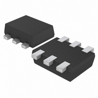
Transistors General purpose transistor (isolated transistors) EMD29 DTB513Z and DTC114E A are housed independently in a EMT6 package. Applications converter Motor driver Features 1) DTr : PNP digital transistor 1 DTr : NPN digital transistor 2 2) ...

Page 2

Transistors Absolute maximum ratings (Ta=25 C) DTr1 Parameter Symbol Supply voltage Input voltage IN Output current I C (MAX.) Power dissipation Junction temperature Tstg Storage temperature ∗ Each terminal mounted on a recommended. DTr2 ...

Page 3

Transistors Electrical characteristics (Ta=25 C) DTr1 Parameter Input voltage Output voltage Input current Output current DC current gain ∗ Transition frequency Input resistance Resistance ratio ∗ Characteristics of built-in transistor. DTr2 Parameter Input voltage Output voltage Input current Output current ...

Page 4

Transistors Electrical characteristic curves DTr1 1000 V = 5[V] CC 100 0.5 1 1.5 INPUT VOLTAGE : V (off 1. 20 0.10 0. 100 1000 OUTPUT ...

Page 5

Transistors DTr2 10m V = Ta=100˚C 1m 25˚C 500μ −40˚C 200μ 100μ 50μ 20μ 10μ 5μ 2μ 1μ 0 0.5 1 1.5 2 2.5 (V) INPUT VOLTAGE : V I (off) Fig.7 Output current vs. input voltage ...

Page 6

Appendix No technical content pages of this document may be reproduced in any form or transmitted by any means without prior permission of ROHM CO.,LTD. The contents described herein are subject to change without notice. The specifications for the product ...

Related keywords