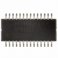
MK74CB218RLFTR IDT, Integrated Device Technology Inc, MK74CB218RLFTR Datasheet - Page 5

MK74CB218RLFTR
Manufacturer Part Number
MK74CB218RLFTR
Description
IC CLOCK DRIVER DUAL 1-8 28-SSOP
Manufacturer
IDT, Integrated Device Technology Inc
Series
74CB, Buffalo™r
Type
Fanout Buffer (Distribution)r
Datasheet
1.MK74CB218RLFTR.pdf
(7 pages)
Specifications of MK74CB218RLFTR
Number Of Circuits
2
Ratio - Input:output
1:8
Differential - Input:output
No/No
Input
LVCMOS
Output
LVCMOS
Frequency - Max
200MHz
Voltage - Supply
3 V ~ 3.6 V
Operating Temperature
0°C ~ 70°C
Mounting Type
Surface Mount
Package / Case
28-SSOP
Frequency-max
200MHz
Number Of Outputs
16
Operating Supply Voltage (max)
3.6V
Operating Temp Range
0C to 70C
Propagation Delay Time
20ns
Operating Supply Voltage (min)
3V
Mounting
Surface Mount
Pin Count
28
Operating Supply Voltage (typ)
3.3V
Package Type
QSOP
Input Frequency
200MHz
Duty Cycle
60%
Operating Temperature Classification
Commercial
Lead Free Status / RoHS Status
Lead free / RoHS Compliant
Other names
800-1880-2
AC Electrical Characteristics
Thermal Characteristics
IDT™ / ICS™ DUAL 1 TO 8 BUFFALO™ CLOCK DRIVER
MK74CB218
DUAL 1 TO 8 BUFFALO™ CLOCK DRIVER
Unless stated otherwise, VDD = 3.3 V ±10%
Notes:
1. Between any two A outputs, or any two B outputs, with equal loading.
2. Between any clock A output and any clock B output with INA connected to INB, and equal loading.
3. See discussion and graph of speed versus load.
Input Clock Frequency
Propagation Delay, 3.3 V
Output Clock Rise Time
Output Clock Rise Time
Output Clock Fall Time
Output Clock Fall Time
Output Duty Cycle
Output Clock Rising Edge Skew
Output Clock A to B Skew
Output Enable Time
Output Disable Time
Thermal Resistance Junction to
Ambient
Thermal Resistance Junction to Case
Parameter
Parameter
Symbol
F
IN
Symbol
JA
JA
JA
JC
Note 3
With load = 15 pF
20% to 80%, C
VDD = 2.5 V, 20% to
80%, C
80% to 20%, C
VDD = 2.5 V, 80% to
20%, C
VDD = 3.3 V or 2.5 V,
C
At VDD/2, Note 1
At VDD/2, Note 2
OE high to output on
OE low to tri-state
L
=10 pF
Conditions
Still air
1 m/s air flow
3 m/s air flow
L
L
5
=10 pF
=10 pF
Conditions
L
L
=10 pF
=10 pF
Min.
Min.
40
0
Typ.
100
100
50
Typ.
3
1
2
1
2
100
80
67
60
Max.
200
250
250
MK74CB218
60
20
20
Max. Units
6
2
3
2
3
FAN OUT BUFFER
Units
MHz
ns
ns
ns
ns
ns
ps
ps
ns
ns
%
C/W
C/W
C/W
C/W
REV K 051310


