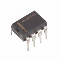
DS1073M-100 Maxim Integrated Products, DS1073M-100 Datasheet - Page 12

DS1073M-100
Manufacturer Part Number
DS1073M-100
Description
ECONOSCILLATOR/DIV 100MHZ 8-DIP
Manufacturer
Maxim Integrated Products
Series
EconOscillator™r
Type
Oscillator, Fixed Frequency, Dualr
Datasheet
1.DS1073M-66.pdf
(18 pages)
Specifications of DS1073M-100
Frequency
100MHz
Voltage - Supply
2.7 V ~ 3.6 V
Current - Supply
25mA
Operating Temperature
-40°C ~ 85°C
Package / Case
8-DIP (0.300", 7.62mm)
Lead Free Status / RoHS Status
Contains lead / RoHS non-compliant
Count
-
DS1073
Read DIV Register [A1H]
This command allows the bus master to read the DS1073’s DIV register.
Write MUX Register [02H]
This command allows the bus master to write to the DS1073’s MUX register.
Read MUX Register [A2H]
This command allows the bus master to read the DS1073’s MUX register.
TRANSACTION/DATA
Immediately following the Function Command, the 9 data bits are written to or read from the DS1073.
This data is written/read lsb first. The following diagrams illustrate the timing. Once data transfer is
complete, a new transaction sequence can be started by re-initializing the device. Therefore to program
both the DIV and MUX registers two complete transaction sequences are required.
READ/WRITE TIME SLOTS
The definitions of write and read time slots are illustrated below. All time slots are initiated by the master
driving the data line low. The falling edge of the data line synchronizes the DS1073 to the master by
triggering a delay circuit in the DS1073. During write time slots, the delay circuit determines when the
DS1073 will sample the data line. For a read data time slot, if a 0 is to be transmitted, the delay circuit
determines how long the DS1073 will hold the data line low overriding the 1 generated by the master. If
the data bit is a 1, the DS1073 will leave the read data time slot unchanged.
WRITE 1 TIME SLOT Figure 14
WRITE 0 TIME SLOT Figure 15
12 of 18


