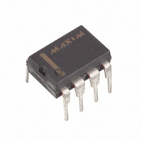
DS1073M-100 Maxim Integrated Products, DS1073M-100 Datasheet - Page 7

DS1073M-100
Manufacturer Part Number
DS1073M-100
Description
ECONOSCILLATOR/DIV 100MHZ 8-DIP
Manufacturer
Maxim Integrated Products
Series
EconOscillator™r
Type
Oscillator, Fixed Frequency, Dualr
Datasheet
1.DS1073M-66.pdf
(18 pages)
Specifications of DS1073M-100
Frequency
100MHz
Voltage - Supply
2.7 V ~ 3.6 V
Current - Supply
25mA
Operating Temperature
-40°C ~ 85°C
Package / Case
8-DIP (0.300", 7.62mm)
Lead Free Status / RoHS Status
Contains lead / RoHS non-compliant
Count
-
Figure 6
SELECT TIMING
If the PDN bit is set to 0, the
externalor crystal reference. The “Enabling Sequencer” is again employed to ensure this transition occurs
in a glitch-free fashion. Two asynchronous clock signals are involved, INTCLK is the internal reference
oscillator divided by one or whatever value of M is selected. EXTCLK is the clock signal fed into the
OSCIN pin, or the clock resulting from a crystal connected between OSCIN and XTAL. The behavior of
OUT0 is described in the following paragraphs, the OUT pin will behavior similarly but will be divided
by N.
FROM INTERNAL TO EXTERNAL CLOCK
This is accomplished by a high to low transition on the
falling edge of INTCLK. The output OUT0 will be held low for a minimum of half the period of
INTCLK (t
switching will not occur until EXTCLK returns to a low level.
Figure 7
Depending on the relative timing of the
cycle of t
pulses will be dependent on the relative timing between t
edge of
minimum values of these parameters are:
NOTE:
In each case there will be a small additional delay due to internal propagation delays.
t
t
t
t
LOW
LOW
SIE
SIE
SELX
I
(min) = t
(max) = 3t
on the output after the falling edge of
I
/2), then if EXTCLK is low it will be routed through to OUT0. If EXTCLK is high the
(min) = t
(max) = t
and the first rising edge of the externally derived clock is t
I
/2
I
I
I
/2
/2 + t
/2 + t
E
E
PDN
/
SELX
SELX
pin can be used to switch between the internal oscillator and an
signal and the internal clock, there may be up to one full
7 of 18
SELX
t
t
t
MAX VALUE OF t
MIN VALUE OF t
M
d
OUTH
= PROP DELAY FROM MCLK TO OUT
. Then, the “low” time (t
= PERIOD OF MCLK
I
SELX
and t
= WIDTH OF OUTPUT PULSE
E
. The time interval between the falling
pin. This transition is detected on the
dis
dis
SIE
= t
= t
SUEM
. Approximate maximum and
SUEM
+ t
+ t
d
d
+ t
+ t
LOW
OUTH
OUTH
) between output
+ t
M


