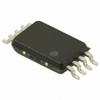
S-35390A-T8T1G Seiko Instruments, S-35390A-T8T1G Datasheet - Page 14

S-35390A-T8T1G
Manufacturer Part Number
S-35390A-T8T1G
Description
IC RTC I2C 2-WIRE 8-TSSOP
Manufacturer
Seiko Instruments
Type
Clock/Calendarr
Datasheet
1.S-35390A-J8T1G.pdf
(56 pages)
Specifications of S-35390A-T8T1G
Time Format
HH:MM:SS (12/24 hr)
Date Format
YY-MM-DD-dd
Interface
I²C, 2-Wire Serial
Voltage - Supply
1.3 V ~ 5.5 V
Operating Temperature
-40°C ~ 85°C
Mounting Type
Surface Mount
Package / Case
8-TSSOP
Function
Clock/Calendar/Alarm/Battery Backup/Interrupt
Supply Voltage (max)
5.5 V
Supply Voltage (min)
1.3 V
Maximum Operating Temperature
+ 85 C
Minimum Operating Temperature
- 40 C
Mounting Style
SMD/SMT
Rtc Bus Interface
Serial (2-Wire, I2C)
Lead Free Status / RoHS Status
Lead free / RoHS Compliant
Memory Size
-
Lead Free Status / Rohs Status
Lead free / RoHS Compliant
Other names
728-1007-2
Available stocks
Company
Part Number
Manufacturer
Quantity
Price
Company:
Part Number:
S-35390A-T8T1G
Manufacturer:
SEIKO
Quantity:
18 700
Part Number:
S-35390A-T8T1G
Manufacturer:
SEIKO
Quantity:
20 000
14
2-WIRE REAL-TIME CLOCK
S-35390A
4. INT1 register and INT2 register
The INT1 and INT2 registers are to set up the output of user-set frequency, or to set up alarm interrupt. Users are able to
switch the output mode by using the status register 2. If selecting to use the output mode for alarm interrupt by status
register 2; these registers work as alarm-time data registers. If selecting the output of user-set frequency by status
register 2; these registers work as data registers to set the frequency for clock output. From each INT1 and INT2 pin,
a clock pulse and alarm interrupt are output.
(1)
INT1 register
Users can set the alarm time (the data of day of the week, hour, minute) by using the INT1 and INT2 registers which
are 3-byte data registers. The configuration of register is as well as the data register of day of the week, hour, minute,
in the real-time data register; is expressed by the BCD code. Do not set a nonexistent day. Users are necessary to
set up the alarm-time data according to the 12/24 hour expression that they set by using the status register 1.
The INT1 register has A1WE, A1HE, A1mE at B0 in each byte. It is possible to make data valid; the data of day of
the week, hour, minute which are in the corresponded byte; by setting these bits to “1”. This is as well in A2WE,
A2HE, A2mE in the INT2 register.
Setting example: alarm time “7:00 pm” in the INT1 register
(a) 12-hour expression (status register 1 B6 = 0)
(b) 24-hour expression (status register 1 B6 = 1)
Alarm interrupt
B7
B7
W1
H1
m1
B7
Day of the week
Day of the week
W2
m2
H2
set up 7:00 PM
Data written to INT1 register
*1. Don’t care (Both of 0 and 1 are acceptable).
set up 19:00 PM
Data written to INT1 register
*1. Don’t care (Both of 0 and 1 are acceptable).
*2. Set up the
W4
m4
H4
Minute
Minute
Hour
Hour
Figure 14 INT1 Register and INT2 Register (Alarm-Time Data)
m8
H8
0
m10 m20 m40
AM /
H10
−
B7
−
B7
0
1
0
1
0
*1
*1
PM
H20
0
−
−
flag along with the time setting.
1
0
0
0
*1
*1
AM /
PM
0
Seiko Instruments Inc.
−
−
1
0
0
0
A1WE
A1mE
A1HE
*1
*1
B0
B0
B0
−
−
0
0
1
0
*1
*1
INT2 register
−
−
0
0
1
0
*1
*1
H1
W1
m1
B7
B7
B7
−
−
0
0
0
0
*1
*1
m2
W2
H2
−
−
1
1
0
0
m4
*1
*1
*2
W4
H4
H8
m8
B0
B0
0
0
1
1
0
1
1
m10 m20 m40
H10
0
H20
0
AM /
PM
Rev.3.0
0
A2HE
A2mE
A2WE
B0
B0
B0
_00


