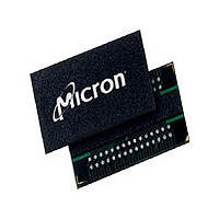
MT47H32M8BP-3:B Micron Technology Inc, MT47H32M8BP-3:B Datasheet - Page 50

MT47H32M8BP-3:B
Manufacturer Part Number
MT47H32M8BP-3:B
Description
Manufacturer
Micron Technology Inc
Type
DDR2 SDRAMr
Datasheet
1.MT47H32M8BP-3B.pdf
(128 pages)
Specifications of MT47H32M8BP-3:B
Organization
32Mx8
Density
256Mb
Address Bus
15b
Access Time (max)
450ps
Maximum Clock Rate
667MHz
Operating Supply Voltage (typ)
1.8V
Package Type
FBGA
Operating Temp Range
0C to 85C
Operating Supply Voltage (max)
1.9V
Operating Supply Voltage (min)
1.7V
Supply Current
190mA
Pin Count
60
Mounting
Surface Mount
Operating Temperature Classification
Commercial
Lead Free Status / Rohs Status
Compliant
Available stocks
Company
Part Number
Manufacturer
Quantity
Price
Company:
Part Number:
MT47H32M8BP-3:B
Manufacturer:
MICRON
Quantity:
586
Company:
Part Number:
MT47H32M8BP-3:B TR
Manufacturer:
Micron Technology Inc
Quantity:
10 000
Table 27: AC Input Test Conditions
PDF: 09005aef8117c187
256MbDDR2.pdf - Rev. M 7/09 EN
Parameter
Input setup timing measurement reference level address
balls, bank address balls, CS#, RAS#, CAS#, WE#, ODT,
DM, UDM, LDM, and CKE
Input hold timing measurement reference level address
balls, bank address balls, CS#, RAS#, CAS#, WE#, ODT,
DM, UDM, LDM, and CKE
Input timing measurement reference level (single-ended)
DQS for x4, x8; UDQS, LDQS for x16
Input timing measurement reference level (differential)
CK, CK# for x4, x8, x16; DQS, DQS# for x4, x8; RDQS,
RDQS# for x8; UDQS, UDQS#, LDQS, LDQS# for x16
Notes:
1. All voltages referenced to V
2. Input waveform setup timing (
3. See Input Slew Rate Derating (page 51).
4. The slew rate for single-ended inputs is measured from DC level to AC level, V
5. Input waveform hold (
6. Input waveform setup timing (
7. Input waveform setup timing (
8. Input waveform timing is referenced to the crossing point level (V
9. The slew rate for differentially ended inputs is measured from twice the DC level to
V
test, as shown in Figure 30 (page 62).
V
to V
Figure 23 (page 54), Figure 25 (page 55), Figure 27 (page 60), and Figure 29
(page 61).
V
test, as shown in Figure 30 (page 62).
referenced from the crossing of DQS, UDQS, or LDQS through the Vref level applied to
the device under test, as shown in Figure 32 (page 63).
is enabled is referenced from the cross-point of DQS/DQS#, UDQS/UDQS#, or LDQS/
LDQS#, as shown in Figure 31 (page 62).
(V
is the complementary input signal, as shown in Figure 33 (page 63).
twice the AC level: 2 × V
V
CK rising edge and would be +250mV to –500mV for CK falling edge.
IH(AC)
IH(AC)
IL(DC)
IH(DC)
TR
REF
and V
level for a rising signal and V
level for a rising signal and V
on the rising edge and V
, the valid intersection is where the “tangent” line intersects V
on the falling edge. For example, the CK/CK# would be –250mV to +500mV for
CP
) applied to the device under test, where V
t
IH
IL(DC)
b
50
Symbol
) timing is referenced from the input signal crossing at the
V
SS
REF(DC)
V
V
V
to 2 × V
.
AC Overshoot/Undershoot Specification
RH
RD
RS
t
t
t
IS
DS) and hold timing (
DS) and hold timing (
IL(AC)
b
) is referenced from the input signal crossing at the
IH(DC)
IL(AC)
Micron Technology, Inc. reserves the right to change products or specifications without notice.
to V
IH(AC)
V
DDQ
256Mb: x4, x8, x16 DDR2 SDRAM
IH(DC)
for a falling signal applied to the device under
for a falling signal applied to the device under
Min
on the rising edge and 2 × V
× 0.49 V
See Note 2
See Note 5
on the falling edge. For signals referenced
V
IX(AC)
DDQ
t
t
DH) for single-ended data strobe is
DH) when differential data strobe
Max
TR
× 0.51
is the true input signal and V
©2003 Micron Technology, Inc. All rights reserved.
IX
Units
) of two input signals
V
V
REF
IL(AC)
, as shown in
to 2 ×
1, 3, 7, 8, 9
IL(DC)
1, 2, 3, 4
1, 3, 4, 5
1, 3, 4, 6
Notes
to
CP


