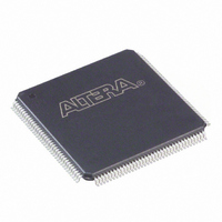
EP2C5T144I8N Altera, EP2C5T144I8N Datasheet - Page 68

EP2C5T144I8N
Manufacturer Part Number
EP2C5T144I8N
Description
IC CYCLONE II FPGA 5K 144-TQFP
Manufacturer
Altera
Series
Cyclone® IIr
Datasheet
1.EP2C5T144C8N.pdf
(168 pages)
Specifications of EP2C5T144I8N
Number Of Logic Elements/cells
4608
Number Of Labs/clbs
288
Total Ram Bits
119808
Number Of I /o
89
Voltage - Supply
1.15 V ~ 1.25 V
Mounting Type
Surface Mount
Operating Temperature
-40°C ~ 100°C
Package / Case
144-TQFP, 144-VQFP
Family Name
Cyclone® II
Number Of Logic Blocks/elements
4608
# I/os (max)
89
Frequency (max)
402.58MHz
Process Technology
90nm
Operating Supply Voltage (typ)
1.2V
Logic Cells
4608
Ram Bits
119808
Operating Supply Voltage (min)
1.15V
Operating Supply Voltage (max)
1.25V
Operating Temp Range
-40C to 100C
Operating Temperature Classification
Industrial
Mounting
Surface Mount
Pin Count
144
Package Type
TQFP
Lead Free Status / RoHS Status
Lead free / RoHS Compliant
Number Of Gates
-
Lead Free Status / Rohs Status
Compliant
Other names
544-2139
Available stocks
Company
Part Number
Manufacturer
Quantity
Price
Company:
Part Number:
EP2C5T144I8N
Manufacturer:
ALTERA41
Quantity:
710
Part Number:
EP2C5T144I8N
Manufacturer:
ALTERA/阿尔特拉
Quantity:
20 000
I/O Structure & Features
2–56
Cyclone II Device Handbook, Volume 1
Cyclone II devices support driver impedance matching to the impedance
of the transmission line, typically 25 or 50 Ω . When used with the output
drivers, on-chip termination sets the output driver impedance to 25 or
50 Ω . Cyclone II devices also support I/O driver series termination
(R
support impedance matching and series termination.
1
On-chip series termination can be supported on any I/O bank. V
V
termination in a given I/O bank. I/O standards that support different R
values can reside in the same I/O bank as long as their V
not conflicting.
1
Impedance matching is implemented using the capabilities of the output
driver and is subject to a certain degree of variation, depending on the
process, voltage and temperature. The actual tolerance is pending silicon
characterization.
Notes to
(1)
(2)
3.3-V LVTTL and LVCMOS
2.5-V LVTTL and LVCMOS
1.8-V LVTTL and LVCMOS
SSTL-2 class I
SSTL-18 class I
Table 2–19. I/O Standards Supporting Series Termination
REF
S
= 50 Ω) for SSTL-2 and SSTL-18.
Supported conditions are V
These R
voltage, and temperature conditions.
must be compatible for all I/O pins in order to enable on-chip series
I/O Standards
Table
The recommended frequency range of operation is pending
silicon characterization.
When using on-chip series termination, programmable drive
strength is not available.
S
values are nominal values. Actual impedance varies across process,
2–19:
CCIO
= V
Target R
CCIO
Table 2–19
25
50
50
50
50
±50 mV.
(2)
(2)
(2)
(2)
(2)
S
(Ω)
lists the I/O standards that
Altera Corporation
CCIO
V
Note (1)
CCIO
February 2007
and V
3.3
2.5
1.8
2.5
1.8
(V)
CCIO
REF
and
are
S


