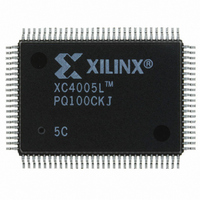
XC4005L-5PQ100C Xilinx Inc, XC4005L-5PQ100C Datasheet - Page 53

XC4005L-5PQ100C
Manufacturer Part Number
XC4005L-5PQ100C
Description
IC 3.3V FPGA 196 CLB'S 100-PQFP
Manufacturer
Xilinx Inc
Series
XC4000r
Datasheet
1.XC4005L-5PC84C.pdf
(175 pages)
Specifications of XC4005L-5PQ100C
Number Of Logic Elements/cells
466
Number Of Labs/clbs
196
Total Ram Bits
6272
Number Of I /o
77
Number Of Gates
5000
Voltage - Supply
3 V ~ 3.6 V
Mounting Type
Surface Mount
Operating Temperature
0°C ~ 85°C
Package / Case
100-BQFP
Lead Free Status / RoHS Status
Contains lead / RoHS non-compliant
Other names
122-1121
Available stocks
Company
Part Number
Manufacturer
Quantity
Price
Table 22: XC4000E Program Data
Notes: 1. Bits per Frame = (10 x number of rows) + 7 for the top + 13 for the bottom + 1 + 1 start bit + 4 error check bits
The MakeBits software creates the configuration bitstream.
In Express mode, only non-CRC error checking is sup-
ported. In all other modes, MakeBits allows a selection of
CRC or non-CRC error checking. The non-CRC error
checking tests for a designated end-of-frame field for each
frame. For CRC error checking, MakeBits calculates a run-
ning CRC and inserts a unique four-bit partial check at the
end of each frame. The 11-bit CRC check of the last frame
of an FPGA includes the last seven data bits.
Detection of an error results in the suspension of data load-
ing and the pulling down of the INIT pin. In Master modes,
CCLK and address signals continue to operate externally.
The user must detect INIT and initialize a new configuration
by pulsing the PROGRAM pin Low or cycling Vcc.
Cyclic Redundancy Check (CRC) for
Configuration and Readback
The Cyclic Redundancy Check is a method of error detec-
tion in data transmission applications. Generally, the trans-
mitting system performs a calculation on the serial
bitstream. The result of this calculation is tagged onto the
data stream as additional check bits. The receiving system
September 18, 1996 (Version 1.04)
Max Logic Gates
CLBs
(Row x Col.)
IOBs
Flip-Flops
Horizontal
Longlines
TBUFs per
Longline
Bits per Frame
Frames
Program Data
PROM Size
(bits)
Device
2. The user can add more “one” bits as leading dummy bits in the header, or, if CRC = off, as trailing dummy bits at the end of
Number of Frames = (36 x number of columns) + 26 for the left edge + 41 for the right edge + 1
Program Data = (Bits per Frame x Number of Frames) + 8 postamble bits
PROM Size = Program Data + 40
any frame, following the four error check bits. However, the Length Count value must be adjusted for all such extra “one”
bits, even for extra leading ones at the beginning of the header.
XC4003E XC4005E/L XC4006E
(10 x 10)
53,936
53,984
3,000
100
360
126
428
80
20
12
(14 x 14)
94,960
95,008
5,000
196
112
616
166
572
28
16
(16 x 16)
119,792
119,840
6,000
256
128
768
186
644
32
18
XC4008E XC4010E/L XC4013E/L XC4020E
(18 x 18)
147,504
147,552
8,000
324
144
936
206
716
performs an identical calculation on the bitstream and com-
pares the result with the received checksum.
Each data frame of the configuration bitstream has four
error bits at the end, as shown in
error is detected during the loading of the FPGA, the con-
figuration process with a potentially corrupted bitstream is
terminated. The FPGA pulls the INIT pin Low and goes into
a Wait state.
During Readback, 11 bits of the 16-bit checksum are added
to the end of the Readback data stream. The checksum is
computed using the CRC-16 CCITT polynomial, as shown
in
icant bits of the 16-bit code. A change in the checksum
indicates a change in the Readback bitstream. A compari-
son to a previous checksum is meaningful only if the read-
back data is independent of the current device state. CLB
outputs should not be included (Read Capture MakeBits
option not used), and if RAM is present, the RAM content
must be unchanged.
Statistically, one error out of 2048 might go undetected.
36
20
Figure
47. The checksum consists of the 11 most signif-
(20 x 20)
178,096
178,144
10,000
1,120
400
160
226
788
40
22
(24 x 24)
247,920
247,968
13,000
1,536
576
192
266
932
48
26
Table
(28 x 28)
329,264
329,312
20,000
2,016
1,076
784
224
306
56
30
21. If a frame data
XC4025E
(32 x 32)
422,128
422,176
25,000
1,024
2,560
1,220
256
346
64
34
4-57


