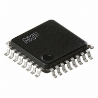
TDA8029HL/C207,118 NXP Semiconductors, TDA8029HL/C207,118 Datasheet - Page 11

TDA8029HL/C207,118
Manufacturer Part Number
TDA8029HL/C207,118
Description
IC SMART CARD READER 32-LQFP
Manufacturer
NXP Semiconductors
Datasheet
1.TDA8029HLC207118.pdf
(59 pages)
Specifications of TDA8029HL/C207,118
Package / Case
32-LQFP
Controller Type
Smart Card Reader Interface
Interface
Serial
Voltage - Supply
2.7 V ~ 6 V
Current - Supply
250mA
Operating Temperature
-40°C ~ 90°C
Mounting Type
Surface Mount
Maximum Operating Temperature
+ 90 C
Minimum Operating Temperature
- 40 C
Mounting Style
SMD/SMT
Lead Free Status / RoHS Status
Lead free / RoHS Compliant
Lead Free Status / RoHS Status
Lead free / RoHS Compliant, Lead free / RoHS Compliant
Other names
568-2233-2
935274733118
TDA8029HL07BD-T
935274733118
TDA8029HL07BD-T
Available stocks
Company
Part Number
Manufacturer
Quantity
Price
Company:
Part Number:
TDA8029HL/C207,118
Manufacturer:
NXP Semiconductors
Quantity:
10 000
Part Number:
TDA8029HL/C207,118
Manufacturer:
NXP/恩智浦
Quantity:
20 000
Philips Semiconductors
9397 750 14145
Product data sheet
8.2 Timer 2 operation
Stop clock mode: The static design enables the clock speed to be reduced down to
0 MHz (stopped). When the oscillator is stopped, the RAM and special function registers
retain their values. This mode allows step-by-step utilization and permits reduced system
power consumption by lowering the clock frequency down to any value. For lowest power
consumption the Power-down mode is suggested.
Idle mode: In the Idle mode, the CPU puts itself to sleep while all of the on-chip
peripherals stay active. The instruction to invoke the Idle mode is the last instruction
executed in the normal operating mode before the Idle mode is activated. The CPU
contents, the on-chip RAM, and all of the special function registers remain intact during
this mode. The Idle mode can be terminated either by any enabled interrupt (at which time
the process is picked up at the interrupt service routine and continued), or by a hardware
reset which starts the processor in the same manner as a Power-on reset.
Power-down mode: To save even more power, a Power-down mode can be invoked by
software. In this mode, the oscillator is stopped and the instruction that invoked
Power-down is the last instruction executed.
Either a hardware reset, external interrupt or reception on RX can be used to exit from
Power-down mode. Reset redefines all the SFRs but does not change the on-chip RAM.
An external interrupt allows both the SFRs and the on-chip RAM to retain their values.
With INT0_N, INT1_N or RX, the bits in register IE must be enabled. Within the INT0_N
interrupt service routine, the controller has to read out the Hardware Status Register
(HSR @ 0Fh) and/or the UART Status register (USR @ 0Eh) by means of
MOVX-instructions in order to know the exact interrupt reason and to reset the interrupt
source.
For enabling a wake up by INT1_N, the bit ENINT1 within UCR2 must be set.
For enabling a wake up by RX, the bits ENINT1 and ENRX within UCR2 must be set.
An integrated delay counter maintains internally INT0_N and INT1_N LOW long enough
to allow the oscillator to restart properly, so a falling edge on pins RX, INT0_N and
INT1_N is enough for awaking the whole circuit.
Once the interrupt is serviced, the next instruction to be executed after RETI will be the
one following the instruction that put the device into power-down.
Table 6:
Timer 2 is a 16-bit timer and counter which can operate as either an event timer or an
event counter, as selected by bit C/T2 in the special function register T2CON. Timer 2 has
three operating modes: capture, auto-reload (up- or down counting), and baud rate
generator, which are selected by bits in register T2CON.
Mode
Idle
Idle
Power-down
Power-down
External pin status during Idle and Power-down mode
Program
memory
internal
external
internal
external
Rev. 03 — 22 February 2005
ALE
1
1
0
0
PSEN_N Port 0
1
1
0
0
data
float
data
float
Low power single card reader
© Koninklijke Philips Electronics N.V. 2005. All rights reserved.
Port 1
data
data
data
data
Port 2
data
address
data
data
TDA8029
Port 3
data
data
data
data
11 of 59


