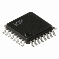
TDA8029HL/C207,118 NXP Semiconductors, TDA8029HL/C207,118 Datasheet - Page 33

TDA8029HL/C207,118
Manufacturer Part Number
TDA8029HL/C207,118
Description
IC SMART CARD READER 32-LQFP
Manufacturer
NXP Semiconductors
Datasheet
1.TDA8029HLC207118.pdf
(59 pages)
Specifications of TDA8029HL/C207,118
Package / Case
32-LQFP
Controller Type
Smart Card Reader Interface
Interface
Serial
Voltage - Supply
2.7 V ~ 6 V
Current - Supply
250mA
Operating Temperature
-40°C ~ 90°C
Mounting Type
Surface Mount
Maximum Operating Temperature
+ 90 C
Minimum Operating Temperature
- 40 C
Mounting Style
SMD/SMT
Lead Free Status / RoHS Status
Lead free / RoHS Compliant
Lead Free Status / RoHS Status
Lead free / RoHS Compliant, Lead free / RoHS Compliant
Other names
568-2233-2
935274733118
TDA8029HL07BD-T
935274733118
TDA8029HL07BD-T
Available stocks
Company
Part Number
Manufacturer
Quantity
Price
Company:
Part Number:
TDA8029HL/C207,118
Manufacturer:
NXP Semiconductors
Quantity:
10 000
Part Number:
TDA8029HL/C207,118
Manufacturer:
NXP/恩智浦
Quantity:
20 000
Philips Semiconductors
Table 52:
Table 53:
9397 750 14145
Product data sheet
Bit
7
6
5
4 and 3
2
1
0
Bit
Symbol
Reset
Access
MSR - mixed status register (address Ch) bit allocation
MSR - mixed status register (address Ch) bit description
8.10.2.3 Mixed status register (MSR)
Symbol
CLKSW
FE
BGT
-
PR1
-
TBE/RBF
CLKSW
7
-
This register relates the status of the card presence contact PR1, the BGT counter, the
FIFO empty indication, the transmit/receive ready indicator TBE/RBF and the completion
of clock switching to or from
FE
6
1
Description
Clock Switch. CLKSW is set when the TDA8029 has performed a required clock switch
from
switch from
Power-down mode or restarting sending commands after leaving power-down (only
needed when the clock is not stopped during power-down). This bit is also reset by RIU
and at power-on. When the microcontroller wants to transmit a character to the card, it
writes the data in direct convention to this register.
FIFO Empty. FE is set when the reception FIFO is empty. It is reset when at least one
character has been loaded in the FIFO.
Block Guard Time.
Not used.
Presence 1. PR1 = 1 when the card is present.
Not used.
Transmit Buffer Empty / Receive Buffer Full. This bit is set when:
This bit is reset:
•
•
•
•
•
•
•
•
In T = 1 protocol, the bit BGT is linked with a 22 ETU counter, which is started at every
start-bit on pin I/O. If the count is finished before the next start-bit, BGT is set. This
helps checking that the card has not answered before 22 ETU after the last transmitted
character, or that the reader is not transmitting a character before 22 ETU after the last
received character.
In T = 0 protocol, the bit BGT is linked to a 16 ETU counter, which is started at every
start-bit on I/O. If the count is finished before the next start-bit, then the bit BGT is set.
This helps checking that the reader is not transmitting too early after the last received
character.
Changing from reception mode to transmission mode
A character has been transmitted by the UART (except when a character has been
parity error free transmitted whilst LCT = 1)
The reception buffer is full.
After power-on
When bit RIU in register CSR is reset
When a character has been written in register UTR
When the character has been read from register URR
When changing from transmission mode to reception mode.
1
n
f
XTAL
BGT
1
5
0
to
2
Rev. 03 — 22 February 2005
f
int
1
2
f
to
int
1
and is reset when the TDA8029 has performed a required clock
n
1
f
XTAL
2
f
int
4
-
-
.
. The application shall wait this bit before entering
read
3
-
-
PR1
Low power single card reader
2
-
© Koninklijke Philips Electronics N.V. 2005. All rights reserved.
1
TDA8029
-
-
TBE/RBF
0
33 of 59
-


