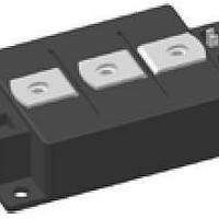
VMM1500-0075X2 IXYS, VMM1500-0075X2 Datasheet - Page 5

VMM1500-0075X2
Manufacturer Part Number
VMM1500-0075X2
Description
MOSFET & Power Driver ICs Dual Pwr Mosfet Mod 75V 1450A
Manufacturer
IXYS
Type
Dual Power MOSFET Driverr
Datasheet
1.VMM1500-0075X2.pdf
(5 pages)
Specifications of VMM1500-0075X2
Product
MOSFET Gate Drivers
Rise Time
1680 ns
Fall Time
880 ns
Maximum Operating Temperature
+ 125 C
Mounting Style
Screw
Package / Case
DIN-970
Maximum Turn-off Delay Time
520 ns
Maximum Turn-on Delay Time
260 ns
Minimum Operating Temperature
- 40 C
Number Of Drivers
2
Number Of Outputs
4
Output Current
500 A
Output Voltage
75 V
Vdss, Max, (v)
75
Id25, Tc = 25°c, (a)
1560
Rds(on), Max, Tj = 25°c, (ohms)
0.38
Ciss, Typ, (pf)
115
Qg, Typ, (nc)
1950
Tf, Typ, (ns)
880
Tr, Typ, (ns)
1680
Pd, (w)
-
Rthjc, Max, (c/w)
0.08
Package Style
Y3-Li (low inductance)
Lead Free Status / Rohs Status
Lead free / RoHS Compliant
© 2010 IXYS All rights reserved
[ns]
[A]
I
t
RM
rr
160
140
120
100
60
40
20
80
V
V
I
0
D
300
400
GS
DS
Fig. 13 Reverse recovery current I
Fig. 15 Reverse recovery time t
Fig. 17 Definition of switching times
0.1 I
0.1 V
V
I
T
V
I
T
F
t
D
VJ
d(on)
VJ
R
R
= 1200 A
= 1200 A
=
= 37 V
= 125°C
= 125°C
D
400
0.9 I
GS
500
37 V
of the body diode vs. di/dt
of the body diode vs. di/dt
t
r
D
500
di
di
F
F
/dt [A/µs]
/dt [A/µs]
600
600
700
700
rr
RM
0.9 V
t
d(off)
800
800
GS
0.9 I
t
f
0.1 I
D
D
t
t
[K/W]
R
thJH
[µC]
[A]
Q
I
S
rr
1200
1000
0.10
0.08
0.06
0.04
0.02
0.00
800
600
400
200
6
5
4
3
2
1
0
0
300
0.0
1
Fig. 14 Reverse recovery charge Q
Fig. 16 Source current I
Fig. 18 Typ. transient thermal impedance
V
I
T
D
VJ
R
0.2
= 1200 A
= 37 V
= 125°C
400
of the body diode vs. di/dt
voltage V
10
VMM 1500-0075X2
0.4
500
di
F
V
SD
t [ms]
/dt [A/µs]
100
SD
0.6
(body diode)
[V]
600
S
vs. source drain
0.8
1000
700
1.0
rr
10000
20100629a
800
1.2
5 - 5


