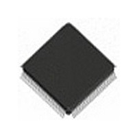
IDT82V2084PF IDT, Integrated Device Technology Inc, IDT82V2084PF Datasheet - Page 11

IDT82V2084PF
Manufacturer Part Number
IDT82V2084PF
Description
IC LIU T1/J1/E1 4CH 128-TQFP
Manufacturer
IDT, Integrated Device Technology Inc
Type
Line Interface Units (LIUs)r
Datasheet
1.IDT82V2084PFG8.pdf
(75 pages)
Specifications of IDT82V2084PF
Protocol
E1
Voltage - Supply
3.13 V ~ 3.47 V
Mounting Type
Surface Mount
Package / Case
128-TQFP, 128-VQFP
Screening Level
Industrial
Mounting
Surface Mount
Package Type
TQFP
Operating Temperature (min)
-40C
Operating Temperature (max)
85C
Lead Free Status / RoHS Status
Contains lead / RoHS non-compliant
Number Of Drivers/receivers
-
Lead Free Status / RoHS Status
Not Compliant, Contains lead / RoHS non-compliant
Other names
82V2084PF
Available stocks
Company
Part Number
Manufacturer
Quantity
Price
Company:
Part Number:
IDT82V2084PF
Manufacturer:
IDT, Integrated Device Technology Inc
Quantity:
10 000
Company:
Part Number:
IDT82V2084PF8
Manufacturer:
IDT, Integrated Device Technology Inc
Quantity:
10 000
Company:
Part Number:
IDT82V2084PFG
Manufacturer:
IDT
Quantity:
650
Company:
Part Number:
IDT82V2084PFG
Manufacturer:
IDT, Integrated Device Technology Inc
Quantity:
10 000
Part Number:
IDT82V2084PFG
Manufacturer:
IDT
Quantity:
20 000
Company:
Part Number:
IDT82V2084PFG8
Manufacturer:
IDT, Integrated Device Technology Inc
Quantity:
10 000
QUAD CHANNEL T1/E1/J1 LONG HAUL/SHORT HAUL LINE INTERFACE UNIT
Table-1 Pin Description (Continued)
SDI/R/W/WR
INT/MOT
DS/RD
Name
SCLK
SDO
RST
INT
CS
D7
D6
D5
D4
D3
D2
D1
D0
A7
A6
A5
A4
A3
A2
A1
A0
Tri-state
Output
Output
Input
Input
Input
Input
Input
Input
Input
Type
I / O
TQFP128
32
33
34
35
36
37
14
15
16
17
18
19
20
21
24
25
26
27
28
29
30
31
38
6
INT/MOT: Intel or Motorola Microcontroller Interface Select
In microcontroller mode, the parallel microcontroller interface is configured for Motorola compatible microcontrollers when this
pin is low, or for Intel compatible microcontrollers when this pin is high.
CS: Chip Select
In microcontroller mode, this pin is asserted low by the microcontroller to enable microcontroller interface. For each read or write
operation, this pin must be changed from high to low, and will remain low until the operation is over.
SCLK: Shift Clock
In serial microcontroller mode, signal on this pin is the shift clock for the serial interface. Configuration data on pin SDI is sampled
on the rising edges of SCLK. Configuration and status data on pin SDO is clocked out of the device on the rising edges of SCLK
if pin SCLKE is low, or on the falling edges of SCLK if pin SCLKE is high.
DS: Data Strobe
In parallel Motorola microcontroller interface mode, signal on this pin is the data strobe of the parallel interface. During a write
operation (R/W =0), data on D[7:0] is sampled into the device. During a read operation (R/W =1), data is output to D[7:0] from
the device.
RD: Read Operation
In parallel Intel microcontroller interface mode, this pin is asserted low by the microcontroller to initiate a read cycle. Data is out-
put to D[7:0] from the device during a read operation.
SDI: Serial Data Input
In serial microcontroller mode, data is input on this pin. Input data is sampled on the rising edges of SCLK.
R/W: Read/Write Select
In parallel Motorola microcontroller interface mode, this pin is low for write operation and high for read operation.
WR: Write Operation
In parallel Intel microcontroller interface mode, this pin is asserted low by the microcontroller to initiate a write cycle. Data on
D[7:0] is sampled into the device during a write operation.
SDO: Serial Data Output
In serial microcontroller mode, signal on this pin is the output data of the serial interface. Configuration and status data on pin
SDO is clocked out of the device on the active edge of SCLK.
INT: Interrupt Request
This pin outputs the general interrupt request for all interrupt sources. If INTM_GLB bit (GCF0, 40H) is set to ‘1’ all the interrupt
sources will be masked. And these interrupt sources also can be masked individually via registers (INTM0, 11H) and (INTM1,
12H). Interrupt status is reported via byte INT_CH (INTCH, 80H), registers (INTS0, 16H) and (INTS1, 17H).
Output characteristics of this pin can be defined to be push-pull (active high or low) or be open-drain (active low) by bits
INT_PIN[1:0] (GCF0, 40H).
Dn: Data Bus 7~0
These pins function as a bi-directional data bus of the microcontroller interface.
An: Address Bus 7~0
These pins function as an address bus of the microcontroller interface.
RST: Hardware Reset
The chip is reset if a low signal is applied on this pin for more than 100ns. All the drivers output are in high-impedance state,
all the internal flip-flops are reset and all the registers are initialized to their default values.
11
Description
TEMPERATURE RANGES
INDUSTRIAL


