DS26519GN+ Maxim Integrated Products, DS26519GN+ Datasheet - Page 44
DS26519GN+
Manufacturer Part Number
DS26519GN+
Description
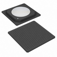
IC TXRX T1/E1/J1 16PRT 484-HSBGA
Manufacturer
Maxim Integrated Products
Type
Transceiverr
Datasheet
1.DS26519GN.pdf
(310 pages)
Specifications of DS26519GN+
Number Of Drivers/receivers
16/16
Protocol
Ethernet
Voltage - Supply
3.135 V ~ 3.465 V
Mounting Type
Surface Mount
Package / Case
484-BGA Exposed Pad, 484-eBGA, 484-HBGA
Lead Free Status / RoHS Status
Lead free / RoHS Compliant


9.8.1.1 Elastic Stores Initialization
There are two elastic store initializations that may be used to improve performance in certain applications: elastic
store reset and elastic store align. Both of these involve the manipulation of the elastic store’s read and write
pointers and are useful primarily in synchronous applications (RSYSCLKn/TSYSCLKn are locked to
RCLKn/TCLKn, respectively). The elastic store reset is used to minimize the delay through the elastic store. The
elastic store align bit is used to center the read/write pointers to the extent possible.
Table 9-4. Elastic Store Delay After Initialization
Receive Elastic Store Reset
Transmit Elastic Store Reset
Receive Elastic Store Align
Transmit Elastic Store Align
N = 9 for RSZS = 0; N = 2 for RSZS = 1
9.8.1.2 Minimum Delay Mode
Elastic store minimum delay mode may be used when the elastic store’s system clock is locked to its network clock
(i.e., RCLKn locked to RSYSCLKn for the receive side and TCLKn locked to TSYSCLKn for the transmit side).
RESCR
maximum depth of 32 bits instead of the normal two-frame depth. This feature is useful primarily in applications that
interface to a 2.048MHz bus. Certain restrictions apply when minimum delay mode is used. In addition to the
restriction mentioned above, RSYNCn must be configured as an output when the receive elastic store is in
minimum delay mode, and TSYNCn must be configured as an output when transmit minimum delay mode is
enabled. In this mode, the SYNC outputs are always in frame mode (multiframe outputs are not allowed). In a
typical application RSYSCLKn and TSYSCLKn are locked to RCLKn, and RSYNCn (frame output mode) is
connected to TSSYNCIOn (frame input mode). The slip zone select bit (RSZS at RESCR.4) must be set to 1. All
the slip contention logic in the framer is disabled (since slips cannot occur). On power-up after the RSYSCLKn and
TSYSCLKn signals have locked to their respective network clock signals, the elastic store reset bit (RESCR.2)
should be toggled from a zero to a one to ensure proper operation.
9.8.1.3 Additional Receive Elastic Store Information
If the receive-side elastic store is enabled, then the user must provide either a 1.544MHz or 2.048MHz clock at the
RSYSCLKn pin. See Section
providing a frame/multiframe sync at the RSYNCn pin or having the RSYNCn pin provide a pulse on
frame/multiframe boundaries. If signaling reinsertion is enabled, the robbed-bit signaling data is realigned to the
multiframe sync input on RSYNCn. Otherwise, a multiframe sync input on RSYNCn is treated as a simple frame
boundary by the elastic store. The framer will always indicate frame boundaries on the network side of the elastic
store via the RFSYNCn output whether the elastic store is enabled or not. Multiframe boundaries will always be
indicated via the RMSYNCn output. If the elastic store is enabled, then RMSYNCn will output the multiframe
boundary on the backplane side of the elastic store. When the device is receiving T1 and the backplane is enabled
for 2.048MHz operation, the RMSYNCn signal will output the T1 multiframe boundaries as delayed through the
elastic store. When the device is receiving E1 and the backplane is enabled for 1.544MHz operation, the
RMSYNCn signal will output the E1 multiframe boundaries as delayed through the elastic store.
If the user selects to apply a 2.048MHz clock to the RSYSCLKn pin, the user can use the backplane blank channel
select registers (RBCS1–4) to determine which channels will have the data output at RSERn forced to all ones.
INITIALIZATION
enables the receive elastic store minimum delay mode. When enabled, the elastic stores will be forced to a
9.8.2
REGISTER BIT
for higher rate system clock applications. The user has the option of either
RESCR.2
RESCR.3
TESCR.2
TESCR.3
44 of 310
N bytes < Delay < 1 Frame + N bytes
N bytes < Delay < 1 Frame + N bytes
1/2 Frame < Delay < 1 1/2 Frames
1/2 Frame < Delay < 1 1/2 Frames
DELAY
DS26519 16-Port T1/E1/J1 Transceiver
Related parts for DS26519GN+
Image
Part Number
Description
Manufacturer
Datasheet
Request
R

Part Number:
Description:
Ds26519 16-port T1/e1/j1 Transceiver
Manufacturer:
Maxim Integrated Products, Inc.
Datasheet:
Part Number:
Description:
power light source LUXEON® Collimator
Manufacturer:
LUMILEDS [Lumileds Lighting Company]
Datasheet:

Part Number:
Description:
MAX7528KCWPMaxim Integrated Products [CMOS Dual 8-Bit Buffered Multiplying DACs]
Manufacturer:
Maxim Integrated Products
Datasheet:
Part Number:
Description:
Single +5V, fully integrated, 1.25Gbps laser diode driver.
Manufacturer:
Maxim Integrated Products
Datasheet:
Part Number:
Description:
Single +5V, fully integrated, 155Mbps laser diode driver.
Manufacturer:
Maxim Integrated Products
Datasheet:
Part Number:
Description:
VRD11/VRD10, K8 Rev F 2/3/4-Phase PWM Controllers with Integrated Dual MOSFET Drivers
Manufacturer:
Maxim Integrated Products
Datasheet:
Part Number:
Description:
Highly Integrated Level 2 SMBus Battery Chargers
Manufacturer:
Maxim Integrated Products
Datasheet:
Part Number:
Description:
Current Monitor and Accumulator with Integrated Sense Resistor; ; Temperature Range: -40°C to +85°C
Manufacturer:
Maxim Integrated Products
Part Number:
Description:
TSSOP 14/A°/RS-485 Transceivers with Integrated 100O/120O Termination Resis
Manufacturer:
Maxim Integrated Products
Part Number:
Description:
TSSOP 14/A°/RS-485 Transceivers with Integrated 100O/120O Termination Resis
Manufacturer:
Maxim Integrated Products
Part Number:
Description:
QFN 16/A°/AC-DC and DC-DC Peak-Current-Mode Converters with Integrated Step
Manufacturer:
Maxim Integrated Products
Part Number:
Description:
TDFN/A/65V, 1A, 600KHZ, SYNCHRONOUS STEP-DOWN REGULATOR WITH INTEGRATED SWI
Manufacturer:
Maxim Integrated Products
Part Number:
Description:
Integrated Temperature Controller f
Manufacturer:
Maxim Integrated Products
Part Number:
Description:
SOT23-6/I°/45MHz to 650MHz, Integrated IF VCOs with Differential Output
Manufacturer:
Maxim Integrated Products