DS26519GN+ Maxim Integrated Products, DS26519GN+ Datasheet - Page 74
DS26519GN+
Manufacturer Part Number
DS26519GN+
Description
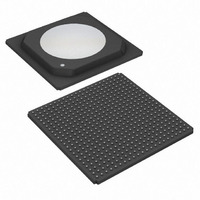
IC TXRX T1/E1/J1 16PRT 484-HSBGA
Manufacturer
Maxim Integrated Products
Type
Transceiverr
Datasheet
1.DS26519GN.pdf
(310 pages)
Specifications of DS26519GN+
Number Of Drivers/receivers
16/16
Protocol
Ethernet
Voltage - Supply
3.135 V ~ 3.465 V
Mounting Type
Surface Mount
Package / Case
484-BGA Exposed Pad, 484-eBGA, 484-HBGA
Lead Free Status / RoHS Status
Lead free / RoHS Compliant


9.9.7.1 Status and Information Bit Operation
When a particular event has occurred (or is occurring), the appropriate bit in one of these registers will be set to a
one. Status bits may operate in either a latched or real-time fashion. Some latched bits may be enabled to generate
a hardware interrupt via the INTB signal.
9.9.7.1.1 Real-Time Bits
Some status bits operate in a real-time fashion. These bits are read-only and indicate the present state of an alarm
or a condition. Real-time bits will remain stable, and valid during the host read operation. The current value of the
internal status signals can be read at any time from the real-time status registers without changing any the latched
status register bits.
9.9.7.1.2 Latched Bits
When an event or an alarm occurs and a latched bit is set to a one, it will remain set until cleared by the user.
These bits typically respond on a change-of-state for an alarm, condition, or event; and operate in a read-then-write
fashion. The user should read the value of the desired status bit, and then write a 1 to that particular bit location in
order to clear the latched value (write a 0 to locations not to be cleared). Once the bit is cleared, it will not be set
again until the event has occurred again.
9.9.7.1.3 Mask Bits
Some of the alarms and events can be either masked or unmasked from the interrupt pin via the Receive Interrupt
Mask Registers (RIM1, RIM3, RIM4, RIM5, RIM7). When unmasked, the INTB signal will be forced low when the
enabled event or condition occurs. The INTB pin will be allowed to return high (if no other unmasked interrupts are
present) when the user reads then clears (with a write) the alarm bit that caused the interrupt to occur. Note that
the latched status bit and the INTB pin will clear even if the alarm is still present.
Note that some conditions may have multiple status indications. For example, receive loss of frame (RLOF)
provides the following indications:
RRTS1.0
(RLOFD)
(RLOFC)
(RLOF)
RLS1.0
RLS1.4
Real-time indication that the receiver is not synchronized
with incoming data stream. Read-only bit that remains high
as long as the condition is present.
Latched indication that the receiver has lost synchronization
since the bit was last cleared. Bit will clear when written by
the user, even if the condition is still present (rising edge
detect of RRTS1.0).
Latched indication that the receiver has reacquired
synchronization since the bit was last cleared. Bit will clear
when written by the user, even if the condition is still
present (falling edge detect of RRTS1.0).
74 of 310
DS26519 16-Port T1/E1/J1 Transceiver
Related parts for DS26519GN+
Image
Part Number
Description
Manufacturer
Datasheet
Request
R

Part Number:
Description:
Ds26519 16-port T1/e1/j1 Transceiver
Manufacturer:
Maxim Integrated Products, Inc.
Datasheet:
Part Number:
Description:
power light source LUXEON® Collimator
Manufacturer:
LUMILEDS [Lumileds Lighting Company]
Datasheet:

Part Number:
Description:
MAX7528KCWPMaxim Integrated Products [CMOS Dual 8-Bit Buffered Multiplying DACs]
Manufacturer:
Maxim Integrated Products
Datasheet:
Part Number:
Description:
Single +5V, fully integrated, 1.25Gbps laser diode driver.
Manufacturer:
Maxim Integrated Products
Datasheet:
Part Number:
Description:
Single +5V, fully integrated, 155Mbps laser diode driver.
Manufacturer:
Maxim Integrated Products
Datasheet:
Part Number:
Description:
VRD11/VRD10, K8 Rev F 2/3/4-Phase PWM Controllers with Integrated Dual MOSFET Drivers
Manufacturer:
Maxim Integrated Products
Datasheet:
Part Number:
Description:
Highly Integrated Level 2 SMBus Battery Chargers
Manufacturer:
Maxim Integrated Products
Datasheet:
Part Number:
Description:
Current Monitor and Accumulator with Integrated Sense Resistor; ; Temperature Range: -40°C to +85°C
Manufacturer:
Maxim Integrated Products
Part Number:
Description:
TSSOP 14/A°/RS-485 Transceivers with Integrated 100O/120O Termination Resis
Manufacturer:
Maxim Integrated Products
Part Number:
Description:
TSSOP 14/A°/RS-485 Transceivers with Integrated 100O/120O Termination Resis
Manufacturer:
Maxim Integrated Products
Part Number:
Description:
QFN 16/A°/AC-DC and DC-DC Peak-Current-Mode Converters with Integrated Step
Manufacturer:
Maxim Integrated Products
Part Number:
Description:
TDFN/A/65V, 1A, 600KHZ, SYNCHRONOUS STEP-DOWN REGULATOR WITH INTEGRATED SWI
Manufacturer:
Maxim Integrated Products
Part Number:
Description:
Integrated Temperature Controller f
Manufacturer:
Maxim Integrated Products
Part Number:
Description:
SOT23-6/I°/45MHz to 650MHz, Integrated IF VCOs with Differential Output
Manufacturer:
Maxim Integrated Products