DS92LV16TVHG/NOPB National Semiconductor, DS92LV16TVHG/NOPB Datasheet - Page 15
DS92LV16TVHG/NOPB
Manufacturer Part Number
DS92LV16TVHG/NOPB
Description
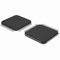
IC SERDES LVDS 16BIT BUS 80-LQFP
Manufacturer
National Semiconductor
Datasheet
1.DS92LV16TVHGNOPB.pdf
(19 pages)
Specifications of DS92LV16TVHG/NOPB
Function
Serializer/Deserializer
Data Rate
2.56Gbps
Input Type
LVTTL/LVCMOS
Output Type
LVTTL, LVCMOS
Number Of Inputs
1
Number Of Outputs
16
Voltage - Supply
3.15 V ~ 3.45 V
Operating Temperature
-40°C ~ 85°C
Mounting Type
Surface Mount
Package / Case
80-LQFP
No. Of Inputs
16
No. Of Outputs
16
Supply Voltage Range
3.15V To 3.45V
Driver Case Style
QFP
No. Of Pins
80
Msl
MSL 3 - 168 Hours
Filter Terminals
SMD
Rohs Compliant
Yes
Data Rate Max
1280Mbps
For Use With
BLVDS16EVK - BOARD EVAL FOR DS92LV16
Lead Free Status / RoHS Status
Lead free / RoHS Compliant
Other names
*DS92LV16TVHG
*DS92LV16TVHG/NOPB
DS92LV16TVHG
*DS92LV16TVHG/NOPB
DS92LV16TVHG
Available stocks
Company
Part Number
Manufacturer
Quantity
Price
Company:

Part Number:
DS92LV16TVHG/NOPB
Manufacturer:
NSC
Quantity:
251
Company:
Part Number:
DS92LV16TVHG/NOPB
Manufacturer:
Texas Instruments
Quantity:
10 000


Application Information
Lock can be regained at the Deserializer by causing the
Serializer to resend SYNC patterns as described above or
by random lock which can take more time depending upon
the data patterns being received.
Input Failsafe
In the event that the Deserializer is disconnected from the
Serializer, the failsafe circuitry is designed to reject certain
amount of noise from being interpreted as data or clock. The
outputs will be tri-stated and the Deserializer will lose lock.
Hot Insertion
All the LVDS devices are hot pluggable if you follow a few
rules. When inserting, ensure the Ground pin(s) makes con-
tact first, then the VCC pin(s), then the I/O pins. When
removing, the I/O pins should be unplugged first, then the
VCC, then the Ground.
PCB Layout and Power System Considerations
Circuit board layout and stack-up for the BLVDS devices
should be designed to provide low-noise power feed to the
device. Good layout practice will also separate high-
frequency or high-level inputs and outputs to minimize un-
wanted stray noise pickup, feedback and interference.
Power system performance may be greatly improved by
using thin dielectrics (2 to 4 mils) for power / ground sand-
wiches. This arrangement provides plane capacitance for
the PCB power system with low-inductance parasitic, espe-
cially proven effective at high frequencies above approx
50MHz, and makes the value and placement of external
bypass capacitors less critical. External bypass capacitors
should include both RF ceramic and tantalum electrolytic
types. RF capacitors may use values in the range of 0.01 uF
to 0.1 uF. Tantalum capacitors may be in the 2.2 uF to 10 uF
range. Voltage rating of the tantalum capacitors should be at
least 5X the power supply voltage being used.
It is a recommended practice to use two vias at each power
pin as well as at all RF bypass capacitor terminals. Dual vias
reduce the interconnect inductance by up to half, thereby
reducing interconnect inductance and extending the effec-
tive frequency range of the bypass components. Locate RF
capacitors as close as possible to the supply pins, and use
wide low impedance traces (not 50 Ohm traces). Surface
mount capacitors are recommended due to their smaller
parasitics. When using multiple capacitors per supply pin,
locate the smaller value closer to the pin. A large bulk
capacitor is recommend at the point of power entry. This is
typically in the 50uF to 100uF range and will smooth low
frequency switching noise. It is recommended to connect
power and ground pin straight to the power and ground
plane, with the bypass capacitors connected to the plane
with via on both ends of the capacitor. Connecting power or
ground pin to an external bypass capacitor will increase the
inductance of the path.
A small body size X7R chip capacitor, such as 0603, is
recommended for external bypass. Its small body size re-
duces the parasitic inductance of the capacitor. User must
pay attention to the resonance frequency of these external
bypass capacitors, usually in the range of 20-30MHz range.
To provide effective bypassing, very often, multiple capaci-
tors are used to achieve low impedance between the supply
rails over the frequency of interest. At high frequency, it is
also a common practice to use two via from power and
ground pins to the planes, reducing the impedance at high
frequency.
(Continued)
15
Some devices provide separate power and ground pins for
different portions of the circuit. This is done to isolate switch-
ing noise effects between different sections of the circuit.
Separate planes on the PCB are typically not required. Pin
Description tables typically provide guidance on which circuit
blocks are connected to which power pin pairs. In some
cases, an external filter many be used to provide clean
power to sensitive circuits such as PLLs.
Use at least a four layer board with a power and ground
plane. Locate CMOS (TTL) swings away from the LVDS
lines to prevent coupling from the CMOS lines to the LVDS
lines. Closely-coupled differential lines of 100 Ohms are
typically recommended for LVDS interconnect. The closely-
coupled lines help to ensure that coupled noise will appear
as common-mode and thus is rejected by the receivers. Also
the tight coupled lines will radiate less.
Termination of the LVDS interconnect is required. For point-
to-point applications termination should be located at the
load end. Nominal value is 100 Ohms to match the line’s
differential impedance. Place the resistor as close to the
receiver inputs as possible to minimize the resulting stub
between the termination resistor and receiver.
Additional general guidance can be found in the LVDS Own-
er’s Manual - available in PDF format from the national web
site at: www.national.com/lvds
Specific guidance for this device is provided next:
DS92LV16 BLVDS SER/DES PAIR
General device specific guidance is given below. Exact guid-
ance can not be given as it is dictated by other board level
/system level criteria. This includes the density of the board,
power rails, power supply, and other integrated circuit power
supply needs.
DVDD = Digital section power supply
These pins supply the digital portion of the device and also
receiver output buffers. The TX DVDD is less critical. The RX
DVDD requires more bypass to power the outputs under
synchronous switching conditions. The receiver DVDD pins
power 4 outputs from each DVDD pin. An estimate of local
capacitance required indicates a minimum of 22nF is re-
quired. This is calculated by taking 4 times the maximum
short current (4 X 70 = 280mA) multiplying by the rise time of
the part (4ns) and dividing by the maximum allowed droop in
VDD (assume 50mV) yields 22.4nF. Rounding up to a stan-
dard value, 0.1uF is selected for each DVDD pin.
PVDD = PLL section power supply
The PVDD pin supplies the PLL circuit. Note that the
DS92LV16 has two separate PLLs and supply pins. The
PLL(s) require clean power for the minimization of Jitter. A
supply noise frequency in the 300kHZ to 1MHz range can
cause increased output jitter. Certain power supplies may
have switching frequencies or high harmonic content in this
range. If this is the case, filtering of this noise spectrum may
be required. A notch filter response is best to provide a stable
VDD, suppression of the noise band, and good high-
frequency response (clock fundamental). This may be ac-
complished with a pie filter (CRC or CLC). If employed, a
separate pie filter is recommended for each PLL to minimize
drop in potential due to the series resistance. The pie filter
should be located close to the PVDD power pin. Separate
power planes for the PVDD pins is typically not required.
AVDD = LVDS section power supply
The AVDD pin supplies the LVDS portion of the circuit. The
DS92LV16 has four AVDD pins. Due to the nature of the
design, current draw is not excessive on these pins. A 0.1uF
www.national.com
Related parts for DS92LV16TVHG/NOPB
Image
Part Number
Description
Manufacturer
Datasheet
Request
R

Part Number:
Description:
National Semiconductor [8-Bit D/A Converter]
Manufacturer:
National Semiconductor
Datasheet:
Part Number:
Description:
National Semiconductor [Media Coprocessor]
Manufacturer:
National Semiconductor
Datasheet:
Part Number:
Description:
Digitally Controlled Tone and Volume Circuit with Stereo Audio Power Amplifier, Microphone Preamp Stage and National 3D Sound
Manufacturer:
National Semiconductor
Datasheet:
Part Number:
Description:
Digitally Controlled Tone and Volume Circuit with Stereo Audio Power Amplifier, Microphone Preamp Stage and National 3D Sound
Manufacturer:
National Semiconductor
Datasheet:
Part Number:
Description:
AC97 Rev 2 Codec with Sample Rate Conversion and National 3D Sound
Manufacturer:
National Semiconductor
Part Number:
Description:
Manufacturer:
National Semiconductor
Datasheet:
Part Number:
Description:
Manufacturer:
National Semiconductor
Datasheet:
Part Number:
Description:
General Purpose, Low Voltage, Low Power, Rail-to-Rail Output Operational Amplifiers
Manufacturer:
National Semiconductor
Datasheet:
Part Number:
Description:
8-bit 20 MSPS flash A/D converter.
Manufacturer:
National Semiconductor
Datasheet:
Part Number:
Description:
Low Noise Quad Operational Amplifier
Manufacturer:
National Semiconductor
Datasheet:
Part Number:
Description:
Quad Differential Line Receivers
Manufacturer:
National Semiconductor
Datasheet:
Part Number:
Description:
Quad High Speed Trapezoidal? Bus Transceiver
Manufacturer:
National Semiconductor
Datasheet:
Part Number:
Description:
Dual Line Receiver
Manufacturer:
National Semiconductor
Datasheet:
Part Number:
Description:
TTL to 10k ECL Level Translator with Latch
Manufacturer:
National Semiconductor
Datasheet: