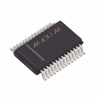
MAX9206EAI+ Maxim Integrated Products, MAX9206EAI+ Datasheet - Page 10

MAX9206EAI+
Manufacturer Part Number
MAX9206EAI+
Description
IC DESERIALIZER LVDS 28-SSOP
Manufacturer
Maxim Integrated Products
Datasheet
1.MAX9206EAI.pdf
(12 pages)
Specifications of MAX9206EAI+
Function
Deserializer
Data Rate
660Mbps
Input Type
LVDS
Output Type
LVTTL, LVCMOS
Number Of Inputs
1
Number Of Outputs
10
Voltage - Supply
3 V ~ 3.6 V
Operating Temperature
-40°C ~ 85°C
Mounting Type
Surface Mount
Package / Case
28-SSOP
Input Current
+/- 15 uA
Input Voltage Range (max)
3.6 V
Interface Type
Parallel LVCMOS/LVTTL
Maximum Operating Temperature
+ 85 C
Minimum Operating Temperature
- 40 C
Mounting Style
SMD/SMT
Operating Supply Voltage
3.3 V
Settling Time
3000 ps
Supply Voltage (max)
3.6 V
Supply Voltage (min)
3 V
Lead Free Status / RoHS Status
Lead free / RoHS Compliant
10-Bit Bus LVDS Deserializers
Figure 9. Input Jitter Tolerance
Bypass each supply pin with high-frequency surface-
mount ceramic 0.1µF and 0.001µF capacitors in paral-
lel as close to the device as possible, with the smaller
valued capacitor the closest to the supply pin.
Trace characteristics affect the performance of the
MAX9206/MAX9208. Use controlled-impedance media.
Avoid the use of unbalanced cables such as ribbon or
Figure 11. Point-to-Point Broadcast Using MAX9150 Repeater
10
______________________________________________________________________________________
Differential Traces and Termination
t
REPEATER
JT
MAX9150
100Ω
MAX9205
MAX9207
Applications Information
t
RCP
/12
ASIC
Power-Supply Bypassing
t
JT
100Ω
V
ID
= 150mV
ASIC
100Ω
MAX9206
MAX9208
simple coaxial cable. Balanced cables such as twisted
pair offer superior signal quality and tend to generate
less EMI due to canceling effects. Balanced cables
tend to pick up noise as common mode, which is
rejected by a differential receiver.
Eliminate reflections and ensure that noise couples as
common mode by running differential traces close
together. Reduce skew by matching the electrical
length of the traces. Excessive skew can result in a
degradation of magnetic field cancellation.
Maintain a constant distance between the differential
traces to avoid discontinuities in differential impedance.
Avoid 90° turns and minimize the number of vias to fur-
ther prevent impedance discontinuities.
Figure 10. Double-Termination Point-to-Point
PARALLEL
DATA IN
MAX9205
MAX9207
100Ω
SERIALIZED DATA
MAX9206
MAX9208
100Ω
ASIC
100Ω
MAX9206
MAX9208
PARALLEL
DATA OUT


