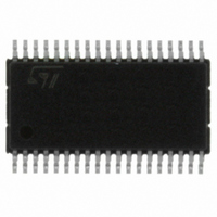
SCLT3-8BT8 STMicroelectronics, SCLT3-8BT8 Datasheet - Page 7

SCLT3-8BT8
Manufacturer Part Number
SCLT3-8BT8
Description
IC SERIAL TERM 8-LINE 38HTSSOP
Manufacturer
STMicroelectronics
Type
Serialr
Datasheet
1.SCLT3-8BT8.pdf
(33 pages)
Specifications of SCLT3-8BT8
Number Of Terminations
8
Voltage - Supply
9 V ~ 35 V
Operating Temperature
-25°C ~ 85°C
Mounting Type
Surface Mount
Package / Case
38-TSSOP Exposed Pad, 38-eTSSOP, 38-HTSSOP
Number Of I/os
8
Operating Supply Voltage
9 V to 35 V
Supply Current (max)
2.3 mA
Maximum Operating Temperature
+ 85 C
Minimum Operating Temperature
- 25 C
Mounting Style
SMD/SMT
Data Bus Width
8 bit, 16 bit
Lead Free Status / RoHS Status
Lead free / RoHS Compliant
Other names
497-10100-5
Available stocks
Company
Part Number
Manufacturer
Quantity
Price
Company:
Part Number:
SCLT3-8BT8
Manufacturer:
AD
Quantity:
6 259
SCLT3-8BT8
2
2.1
2.2
Functional description
Input power section
The SCLT3-8 is an 8-line input termination device designed for 24 V DC automation
applications. It provides the front-end circuitry of a digital input module (I/O) in industrial
automation.
Available in an eight-channel configuration, it offers a high-density termination by minimizing
the conducting dissipation and the external component count.
Made of an input voltage protection, a serial current limiting circuit and an output interface,
each channel circuit terminates the connection between the logic input and its associated
high side sensor or switch.
The SCLT3-8 is an 8-line current limiting input array compatible with type 1 and 3 (>2 mA)
characteristics of the IEC 61131-2 standard.
Each input voltage clamping block protects the module input against electromagnetic
interferences such as those described in the IEC 61131-2 standard and IEC 61000-4-2
(ESD), 4-4 (transient burst), 4-5 (voltage surge) and 4-6 (conducted radio frequency
interferences) standards. The supply input is also designed with such a protection structure.
The current limiting circuit connected between the IN
resistor R
tolerance, the current limitation allows drastic reduction of the input dissipation, 78 mW per
channel in type 3, compared with a resistive input.
Furthermore, the SCLT3-8 is housed in a very low R
mount package that allows the PCB cooling pad to be reduced. The overall module and
printed board size become smaller and the hot spot effect is reduced.
In accordance with IEC 61131-2 standard when the input current is less than 1.5 mA, the
output circuit maintains the associated output data and the visual LED in the OFF state.
When the module input voltage V
corresponding to a SCLT input voltage V
associated output data in ON state.
Visual input LED driver
Since the inputs are indicated with an LED, as described in the IEC 61131-2 standard, an
LED driver is implemented on each input power section.
This driver has two major benefits for the application. First, it takes its electrical energy
directly from the input current. This energy is free being, in any case, dissipated in the SCLT.
Second, it eliminates the need for extra pins on the I/O controller to manage the LED drive.
The LED will be powered when the input voltage V
when the input current is less than 1.5 mA.
The LED diodes will be driven in a low side configuration, all cathodes connected to ground.
This topology naturally protects the LEDs and simplifies their wiring (8 wires plus the ground
wire). When the LEDs are not used, the pins LD
path of the input current.
REF
and is compensated over the full temperature range. Thanks to its 10%
Doc ID 15191 Rev 3
I
, including the 2.2 kΩ input resistor, is higher than 11 V
IN
higher than 5 V, the output circuit puts its
I
are grounded to COM
I
is higher than 11 V, and it is turned off
TH
I
and LD
exposed pad HTSSOP surface
I
pins is set externally by a
Functional description
P
to maintain the
7/33


