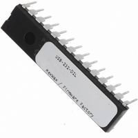
USB-232-DIL Flexipanel, USB-232-DIL Datasheet - Page 10

USB-232-DIL
Manufacturer Part Number
USB-232-DIL
Description
IC USB ASYNC SRL UART 28-DIL
Manufacturer
Flexipanel
Datasheet
1.USB-232-SS.pdf
(11 pages)
Specifications of USB-232-DIL
Applications
USB
Interface
I²C, SPI
Voltage - Supply
3.3 V ~ 5 V
Package / Case
28-DIP
Mounting Type
Through Hole
Lead Free Status / RoHS Status
Lead free / RoHS Compliant
Other names
658-1032-5
Customization
The product can be customized in one of three ways:
Delivery and Programming
USB-232 is available pre-programmed in 28-pin DIL and
20-pin SSOP packages. USB-232-SS (SSOP package)
may be supplied with an ID label, or it may be identified
with a yellow mark on the package.
In high volumes (5K+), USB-232 is available reeled with
your custom settings preloaded, in any available
package.
TEAclipper Programming
If practical, a TEAclipper programming socket should be
added to the circuit board in order to facilitate in-circuit
firmware updates.
During programming, these connections must be
protected against contention.
Vpp is subject to 13V during programming. Nothing else
should be connected to Vpp except via a 22k pull-up
resistor.
The TEAclipper connector format is shown in figure 13.
Since the programming time is fast, no programming
p10 of 11
1. Using the HIDconfig.exe application (figure 12) in
2. By requesting the custom settings to be supplied
3. Using customization commands. Documentation
the development kit. This application makes it
very easy to copy the configuration from an
existing product to a new product and is suitable
for in-factory use. (It cannot be used if you have
changed the Vendor ID and / Product ID.)
pre-programmed when buying pre-programmed
chips (5K units minimum).
on these commands is available on request.
Figure 12. HIDconfig.exe application
(“USB-232 0005”)
26-Aug-10
In particular, note that
USB-232
socket is required.
against the plate-through holes shown.
It is strongly recommended that this connector is
included in circuits even if in-circuit programming is not
anticipated, since this allows you to upgrade the
firmware if necessary.
Evaluation Board
USB-232 may be evaluated with the Firmware Factory
USB Products Eval Board (figure 14). The components
which must be fitted are shown in table 5. In addition,
the following wire links must be made:
- TxD28 to TxD near the MAX222.
- RxD28 to RxD near the MAX222.
- Pin VIO9/CTS (DIL pin 22) to CTS near the MAX222.
- Pin VIO6/RTS (DIL pin 11) to RTS near the MAX222.
- Pin VIO5/Suspend# (DIL pin 24) to SHDN near the
- Pin VIO10/Send (DIL pin 21) to Vin
The prototyping area on the left of the board may be
used to add components to which the expandIO-USB
will interface. In figure 11, an active low LED has been
connected to the AllSysGo# pin and active high LEDs to
the Tx and Rx indicators.
The printed circuit board integrates an edge connector
of USB Type A format. This may be plugged into a USB
extension cable.
Pin 1 indicated
by square pad
C4, C31-C35
Figure 13. Recommended plate-through connector design
MAX222.
- Jumper J to Jumper K (20 pin device only)
- Jumper L to Jumper M (20 pin device only)
HW143-19
C2, C3
Label
PL2
PL6
U2
U4
D2
C7
C8
R2
X1
Table 5. Evaluation Board bill of materials
The TEAclipper can be ‘leaned’
DB9 female socket, right angle
DB9 male socket, right angle
12MHz parallel cut crystal
100nF capacitor
470nF capacitor
2.54mm spacing
10uF capacitor
22pF capacitor
USB-232-DIL
MAX222-DIL
Component
22k resistor
Wire link
www.firmwarefactory.com
1mm hole dia


