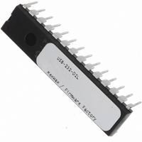
USB-232-DIL Flexipanel, USB-232-DIL Datasheet - Page 8

USB-232-DIL
Manufacturer Part Number
USB-232-DIL
Description
IC USB ASYNC SRL UART 28-DIL
Manufacturer
Flexipanel
Datasheet
1.USB-232-SS.pdf
(11 pages)
Specifications of USB-232-DIL
Applications
USB
Interface
I²C, SPI
Voltage - Supply
3.3 V ~ 5 V
Package / Case
28-DIP
Mounting Type
Through Hole
Lead Free Status / RoHS Status
Lead free / RoHS Compliant
Other names
658-1032-5
plugs. The micro connector pin-out is the same as the
mini connector.
For ultra-low cost products, it is possible to form a USB
Type-A plug direct from a circuit board as shown in
figure 11. This connector is only suitable for a number
of insertions (~50 before cleaning is required).
unshielded and recommended only for ‘dongle’ type
products with no cables attached.
For further dimensional information, refer to figure 6-7 of
the USB 2.0 Specification, in the development kit.
Host-Side Interfacing
USB-232 uses the Human Interface Device (HID) USB
interface. It has the advantages that no device drivers
are required, and that a host application can easily
locate the USB-232.
All exchanges of data (‘reports’) between the host and
the USB-232 are 64 bytes in length, regardless of how
many bytes of meaningful data are actually transferred.
In HID terms, all transfers are 1ms interrupt reports of
64 bytes, to and from output ID 0 on EP1.
The host software has two perform two tasks. First it
has to locate the device. Then it has to communicate
with it. To locate the device, enumerate all devices with
Vendor ID 0x0B40 and Product ID 0x011A (2450-based
devices) or 0x011B (14K50-based devices). Then use a
Get Feature request for the string 4, the Product GUID.
p8 of 11
Std Mini
1
2
3
–
4
Prior to writing your own software, you can use the
Pin
HIDconfig.exe software in the development kit to
evaluate USB-232.
12.00
1
2
3
4
5
0.50
3.00
Figure 10 Common USB pin-outs for male connectors
1.00-2.00
Shoulder required to prevent over-insertion
Name
1.00
1.00
Gnd
Vcc
D–
D+
ID
Overall PCB width 16.00 or less
2.25
Table 5. USB Connection Key
1.25
Cable
Green
White
color
Black
Red
26-Aug-10
–
11.75
Fig 11.
Description
+5V (can dip to 4.08V)
Data –
Data +
Type A: Connect to ground
Type B: Not connected
Signal ground
4. Vss
3. D+
2. D-
1. Vdd
including tracks 2.00 - 2.20
Contacts plated with hard
gold flash (0.25-1.27µm)
over nickel (2.6-5.0µm)
Overall PCB thickness
USB-232
Dimensions in mm
It is
If this matches the product GUID you configured for the
device, you have located it.
Once you have located the device, you need to open a
file to communicate with it. You can then send data and
receive data as 64-byte reports.
Sample source code for Windows and a Windows
dynamic link library (DLL) are provided in the
development kit. For a detailed description, please refer
to the comments embedded in the source code and the
Visual Basic example in the Excel spreadsheet. Sample
source code for Mac OS and Linux is in preparation.
Sending and Receiving Data
The first byte of the report (byte 0) is termed the
identifier. If its value is 0x01-0x3F, then it indicates that
the packet is data for transmission to or received from
the TxD and RxD pins. The value equals the number of
data bytes being transferred. The data is located from
byte 1 of the report onwards.
If its value is 0x41-0x7F, it should be interpreted exactly
the same as 0x01-0x3F except the value equals the
number of data bytes being transferred plus 0x40, and
the report must be acknowledged before the next data
report is sent.
sending a report with an identifier of value 0x40.
(Note: Prior to rev 0008, the maximum number of data
bytes is 0x3E, i.e. the identifiers 0x3F and 7F are not
permitted.)
Break conditions are not supported. Contact us if this is
an important design requirement.
Commands
All commands are sent using identifiers of value 0x80 or
higher. If a response to the command is required, the
response will have the same identifier as the command
to which it is responding. The Interrupt response has no
command associated with it and it may be received by
the host at any time.
Note: Accidentally sending a command in the range
0x80-0x8F can modify settings that may permanently
disable the device. During product development, it is
recommended that you work with a device that has been
write locked using HIDconfig.exe. Devices intended for
production should always be write locked.
Get Pin
The identifier GETPIN (0x90) retrieves value of a pin.
The command payload has one byte, which indicates
the pin, as shown in table 6. The response payload has
two bytes, as shown in table 6.
Example:
Get Analog
The identifier GETANALOG (0x96) retrieves the voltage
of the analog pin. The command has not payload. The
response payload has two bytes, representing a number
90 25
90 25 01
HW143-19
Command – Get DTR pin
Response – Pin is active
A data report is acknowledged by
www.firmwarefactory.com


