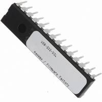
USB-232-DIL Flexipanel, USB-232-DIL Datasheet - Page 3

USB-232-DIL
Manufacturer Part Number
USB-232-DIL
Description
IC USB ASYNC SRL UART 28-DIL
Manufacturer
Flexipanel
Datasheet
1.USB-232-SS.pdf
(11 pages)
Specifications of USB-232-DIL
Applications
USB
Interface
I²C, SPI
Voltage - Supply
3.3 V ~ 5 V
Package / Case
28-DIP
Mounting Type
Through Hole
Lead Free Status / RoHS Status
Lead free / RoHS Compliant
Other names
658-1032-5
Tx / Rx Indication
Output for connecting to a transmit / receive indication
LED. It turns on for approximately 100ms when data
has been transmitted to or received from the host. This
setting is available on any VIO pin except VIO0.
Configured Indication
Output that indicates when the USB interface has
completed configuration and the host has indicated that
the device may draw its full power setting.
configuration completing, the device should draw no
more than 100mA from the bus.
configured indication continues to stay high when in
suspend mode, even though the device must consume
no more than 100μA during suspend. This setting is
available on any VIO pin except VIO0. Refer to table 3.
Suspend Indication
Output that indicates when the host is entering a sleep
state (active low). In this state, the device should draw
no more than 100μA from the bus, excluding the
consumption of the USB-232 chip.
available on any VIO pin except VIO0. Refer to table 3.
Host Ready Indication
Output that indicates when an application has signaled
that it has located the device, and it is available for
communication. This setting is available on any VIO pin
except VIO0. Refer to table 3.
Low Power Indication
Output which is high when the device must draw no
more than 100mA from the bus, rather than the
maximum power it has been configured for. This setting
is available on any VIO pin except VIO0. Refer table 3.
All-Systems-Go Indication
Output that indicates when the USB-232 is configured
and not suspended. This setting is available on any VIO
pin except VIO0. Refer to table 3.
DTR
Standard RS232 handshaking output pin. The host can
set the state of this pin with the Set Pin command. This
setting is available on any VIO pin except VIO0. This
signal is normally active low.
DCD, DSR, RI
Standard RS232 handshaking input pins. The host can
determine the state of these pins with the Get Pin
command. This setting is available on any VIO pin.
These signals are normally active low.
p3 of 11
Pin
Configured
Suspend#
Low Pwr
All Sys Go#
Host Rdy
Table 3. USB Status Indication Logic
Initial-
izing
0
1
1
1
0
26-Aug-10
‡ HP = Plugged direct into host or powered hub
LP †
Initialized
1
1
1
0
0
† LP = Plugged into unpowered hub
HP ‡
1
1
0
0
0
LP †
Host App
Running
1
1
1
0
1
This setting is
Note that the
HP ‡
USB-232
1
1
0
0
1
Prior to
Sleep
Host
1
0
1
1
0
CTS, RTS
Standard RS232 hardware flow control pins. RTS is an
output, indicating that serial data may be sent to the
device. It will transition to inactive when only 16 bytes of
buffer space remain. It will transition to active when 32
or more bytes of buffer space remain. Data sent while
buffer space remains will be accepted, even if RTS is
inactive.
discarded; it does not overwrite data already in the
buffer.
CTS is an input, indicating that serial data may be
transmitted by the device. It is possible that a single
byte may start to be transmitted up to 30μs after CTS
has transitioned to the inactive state.
If hardware flow control is not specified, the output state
of the RTS pin can be controlled using the Set Pin
command.
VIO0. CTS must be on VIO9 or VIO10. These signals
are normally active low.
Buffer Empty
Output that indicates that there is no buffered data from
the host waiting to be output through the serial port.
This pin will change to low as soon as data is added to
the buffer, and to high as soon as the last byte starts to
be output from the serial port. This setting is available
on any VIO pin except VIO0.
Tx Enable
Output which is active when data is being transmitted
from TxD. It goes high immediately prior to the first byte
being transmitted and will not go low again until all
available data has been transmitted. It goes low half
way through the last stop bit. If this causes difficulties,
specify two stop bits. This setting is available on any
VIO pin except VIO0.
Send
Send is an input which controls when data is transmitted
to the host. This pin is normally held in the active state.
In this state, data is buffered until 63 bytes have arrived
or a one-character-long quiet period occurs.
If the send pin is inactive, data will be buffered and will
not be transmitted to the host. If the pin transitions to
the active state, an interrupt will be generated and the
data will be sent to the host immediately. Send must be
on VIO9 or VIO10.
Digital Input
Digital Input is a general purpose input. Its state can be
read using the Get Pin command.
available on any VIO pin.
Digital Output
Digital Output is a general purpose output. Its state can
be set using the Set Pin command and read using the
Get Pin command.
initialize to the inactive state. This setting is available on
any VIO pin except VIO0.
HW143-19
If data is sent after the buffer is full, it is
RTS is available on any VIO pin except
On power-up and reset, it will
www.firmwarefactory.com
This setting is


