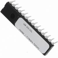
USB-232-DIL Flexipanel, USB-232-DIL Datasheet - Page 7

USB-232-DIL
Manufacturer Part Number
USB-232-DIL
Description
IC USB ASYNC SRL UART 28-DIL
Manufacturer
Flexipanel
Datasheet
1.USB-232-SS.pdf
(11 pages)
Specifications of USB-232-DIL
Applications
USB
Interface
I²C, SPI
Voltage - Supply
3.3 V ~ 5 V
Package / Case
28-DIP
Mounting Type
Through Hole
Lead Free Status / RoHS Status
Lead free / RoHS Compliant
Other names
658-1032-5
RS485 Converter
RS485 is a bus configuration which allows each device
to broadcast data to all other devices on the bus via just
two differential lines A and B. Only one device may
transmit at a time.
MAX481 is used to create the A and B signals, as
shown in figure 7.
terminated by 120Ω resistors (i.e. two resistors for the
entire bus). These are not shown in figure 8, but they
are in figure 9.
RS422 Converter
RS422 is similar to RS485 except only two devices
communicate with each other, and use a pair of
differential lines. In this ‘full-duplex’ setup both devices
may transmit at the same time if required. Since the
receiver inputs A and B in figure 9 will be, by definition,
at the end of the ‘bus’, a 120Ω terminating resistor is
required as shown.
control lines RTS and CTS.
second MAX491 can be added.
p7 of 11
Vdd
Vss
Vdd
(Active low shown)
circuit for each input
One LED circuit
(Active low shown)
for each output
One pushbutton
PB1x
R2x
R1x
C8
Vdd
Vss
Buff Empty
Tx Ind
Rx Ind
Reset#
DCD#
DSR#
RI#
Suspend
DTR#
AllSysGo#
Send
C7
Vusb
TEAclipper
26-Aug-10
connector
C6
MAX481
An RS485 converter such as a
Both ends of the bus must be
C1
Figure 9 does not provide flow
1
2
Fig 8
USB-232
3
Gnd
Vcc
4
5
If they are required, a
Vss
OSC2
OSC1
Vdd
Vss
D+
D-
Vdd
Vss
X1
C3
C2
USB-232
4
3
2
1
Vss
USB
Power considerations
Initially, the device will request the full power it is
configured for. If it is not granted this power level within
three seconds, it performs a soft detach and requests a
maximum of 100mA. This allows devices to operate in a
low power mode when connected to an unpowered hub.
This reduced power mode is indicated by the Low Pwr
Indication pin.
In RS232, RS485 and RS422 systems, independently
powered devices may float at different voltages; in
addition exceptional voltages can be introduced from
other sources along the signal lines. Consider adding
current limiting resistors or opto-isolators if this is a
possibility. The shield on the RS232 connector should
be left unconnected.
If the device is electromagnetically noisy, a ferrite bead
is recommended on the USB Vdd supply in order to
suppress any transmission of noise to the rest of the
USB network. 100nF smoothing capacitors should be
provided on all independently switched power rail to
avoid momentary brown-out conditions.
When designing self powered circuits, ensure power can
never be fed into the Vdd USB line.
AN1149 from Microchip Technology, in the development
kit, discusses designs for recharging batteries using
USB bus power.
USB Connectors
Common USB connector and cable configurations are
shown in figure 10 and table 5.
connector should be left unconnected. The ID pin on
the mini connector permits the distinction of A and B
Vdd
Vss
Vdd
(Active low shown)
circuit for each input
One LED circuit
(Active low shown)
for each output
One pushbutton
PB1x
HW143-19
R2x
R1x
A & B at the other
Connect X & Y
at one end to
C8
Vdd
Vss
Vusb
AllSysGo#
Buff Empty
Tx Ind
Rx Ind
Reset#
DCD#
DSR#
RI#
Suspend
DTR#
Send
C7
TEAclipper
connector
C6
MAX491
C1
1
Fig 9.
2
USB-232
3
Vcc
Gnd
4
5
R7
www.firmwarefactory.com
Vss
The shield on the
OSC2
OSC1
Vdd
Vss
D+
D-
Design note
Vdd
Vss
X1
C3
C2
4
3
2
1
Vss
USB


