USB-232-DIL Flexipanel, USB-232-DIL Datasheet - Page 2
USB-232-DIL
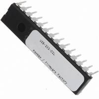
Manufacturer Part Number
USB-232-DIL
Description
IC USB ASYNC SRL UART 28-DIL
Manufacturer
Flexipanel
Datasheet
1.USB-232-SS.pdf
(11 pages)
Specifications of USB-232-DIL
Applications
USB
Interface
I²C, SPI
Voltage - Supply
3.3 V ~ 5 V
Package / Case
28-DIP
Mounting Type
Through Hole
Lead Free Status / RoHS Status
Lead free / RoHS Compliant
Other names
658-1032-5


Basic Operation
To the electronic system (‘device’), USB-232 looks like a
serial UART. To the PC (‘host’), it looks like a Human
Interface Device (HID) with which it may exchange
information using simple commands.
Using the HID USB profile means that no driver
installation is required and immediate compatibility is
assured
Additionally, software can find the device automatically
without needing to know which virtual COM port it is
occupying.
Pin Functions
The pin functions are shown in table 2. The function of
the virtual I/O pins is reconfigurable, so their default
settings are also shown. The output pins are in a tri-
state condition until ~20μs after power-on.
The pin functions are described in detail below.
Vss, Vdd, Vusb
Vss is the power supply ground reference. Vdd should
be connected to a regulated supply, for example the
p2 of 11
2450 14K50
8,19
DIL
23
24
17
11
18
12
13
22
21
25
26
14
15
27
16
28
20
10
1
5
6
7
9
SSOP
10
11
12
13
14
15
16
17
18
19
20
4
5
6
7
8
9
1
3
2
on
Name Description
VIO10 Virtual I/O / *Send (in)
VIO11 Virtual I/O / *Tx Ind (out)
VIO12 Virtual I/O / *Rx Ind (out)
OSC1 Oscillator output
OSC2 Oscillator input
VIO0
VIO1
VIO2
VIO3
VIO4
VIO5
VIO6
VIO7
VIO8
VIO9
Vusb
PGC
PGD
RxD
TxD
Vpp
Vss
Vdd
Windows,
D+
D-
26-Aug-10
Virtual I/O / *Reset# (in)
TEAclipper Vpp
Virtual I/O / *DCD# (in)
Virtual I/O / *DSR# (in)
Virtual I/O / *RI# (in)
Virtual I/O / *DTR# (out)
Virtual I/O / *Suspend# (out)
Serial data (out) #
Virtual I/O / *RTS# flow control (out)
Serial data (in) #
Virtual I/O / *All-Systems-Go# (out)
Virtual I/O / *Buffer Empty (out)
Virtual I/O / *CTS# flow control (in)
USB supply filter
USB data -
TEAclipper PGC
USB data+
TEAclipper PGD
Power ground reference
Power positive input
Table 2. Device Pinout
Linux
and
* = default configuration
OS
# = active low
USB-232
systems.
USB bus power.
470nF capacitor, to Vss. See for example C8 in figure 2.
OSC1, OSC2
OSC1 and OSC2 should be connected to a 12MHz
parallel cut crystal circuit with 22pF capacitors. It may
be replaced with a 12MHz resonator with 0.25% total
tolerance.
RxD, TxD
Active low serial data input and output.
Vpp, PGC, PCD
TEAclipper programming pins.
and Programming section for details. Note that the Vpp
pin may be subject to voltages as high as 12V during
programming.
VIO pins
The VIO pin functions can be reconfigured as detailed in
the customization section.
shown in table 2. The pins can be configured as follows.
No Function
The pin is a digital input that has no effect. To minimize
power consumption, it should be biased high or low.
This setting is available on all VIOs.
Reset
The pin is an active low reset input.
device effectively implements the soft detach function.
This setting is available on VIO0 only.
USB Power Sense
If the device is capable of operating while not plugged
into a USB port, a USB Power Sense input should be
provided.
detected on the V+ pin of the USB connector. It is used
to reduce power consumption by entering into a sleep
mode when the USB is not present, and also to ensure
that the USB engine correctly initializes when the device
is plugged in. The UART is not operational during sleep.
This setting must be on VIO9 or VIO10.
Self Power Sense
If the device is capable of operating while not plugged
into a USB port, a Self Power Sense input may be
provided. This pin should indicate when the device is
not drawing power from the USB bus and can help the
PC manage its power budget. This setting is available
on any VIO pin.
Tx Indication
Output for connecting to a transmit indication LED. It
turns on for approximately 100ms when data has been
transmitted to the host. This setting is available on any
VIO pin except VIO0.
Rx Indication
Output for connecting to a receive indication LED. It
turns on for approximately 100ms when data has been
received from the host. This setting is available on any
VIO pin except VIO0.
HW143-19
This pin should indicate that a voltage is
Vusb should be connected, via a
The default functions are
www.firmwarefactory.com
Refer to the Delivery
Resetting the
Related parts for USB-232-DIL
Image
Part Number
Description
Manufacturer
Datasheet
Request
R

Part Number:
Description:
IC USB ASYNC SRL UART 20-SSOP
Manufacturer:
Flexipanel
Datasheet:

Part Number:
Description:
USB
Manufacturer:
Samtec Inc
Datasheet:

Part Number:
Description:
KIT REF DES USB MASS STORAGE
Manufacturer:
Silicon Laboratories Inc
Datasheet:
Part Number:
Description:
Manufacturer:
Samtec Inc
Datasheet:

Part Number:
Description:
USB TO I2C INTERFACE
Manufacturer:
Analog Devices
Datasheet:


Part Number:
Description:
USB Interface IC USB to RS232Retrofit Adapter DB9 Male
Manufacturer:
FTDI
Datasheet:

Part Number:
Description:
USB Interface IC USB to RS232Retrofit Adapter DB9 Female
Manufacturer:
FTDI
Datasheet:

Part Number:
Description:
USB & Firewire Connectors USB TYPE A DUAL PORT 4P RT ANG THRU HL
Manufacturer:
ADAM TECH
Datasheet:
Part Number:
Description:
USB & Firewire Connectors USB TYPE A 4P RIGHT ANGLE UPRIGHT
Manufacturer:
ADAM TECH
Datasheet:
Part Number:
Description:
USB & Firewire Connectors USB TYPE A 4P RIGHT ANGLE SMT
Manufacturer:
ADAM TECH
Datasheet:
Part Number:
Description:
USB Interface IC Driver-free USB I/O- expander
Manufacturer:
Flexipanel
Datasheet:
Part Number:
Description:
USB Interface IC Driver-free USB I/O- expander
Manufacturer:
Flexipanel
Datasheet:
Part Number:
Description:
USB Interface IC Driver-free USB I/O- expander
Manufacturer:
Flexipanel
Datasheet: