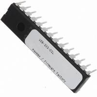
USB-232-DIL Flexipanel, USB-232-DIL Datasheet - Page 5

USB-232-DIL
Manufacturer Part Number
USB-232-DIL
Description
IC USB ASYNC SRL UART 28-DIL
Manufacturer
Flexipanel
Datasheet
1.USB-232-SS.pdf
(11 pages)
Specifications of USB-232-DIL
Applications
USB
Interface
I²C, SPI
Voltage - Supply
3.3 V ~ 5 V
Package / Case
28-DIP
Mounting Type
Through Hole
Lead Free Status / RoHS Status
Lead free / RoHS Compliant
Other names
658-1032-5
Manufacturer Name
The manufacturer name is a Unicode string of up to 61
characters plus zero terminator. The host application
can read this data using a Get Feature request for string
2. The host PC commonly displays this string while it is
installing the default HID driver when it is first inserted.
Unless otherwise configured, the default value is
“Firmware Factory Ltd”.
Serial Number
The Serial Number data is a Unicode string of up to 61
characters plus zero terminator. The host application
can read this data using a Get Feature request for string
3. The Serial Number is a unique string which you can
use to differentiate one physical device from other
devices with the same USB-232 Vendor ID / Product ID
/ Product GUID combination.
configured, the default value is a unique value.
Product GUID
The product GUID is a Unicode string of up to 61
characters plus zero terminator. The host application
can read this data using a Get Feature request for string
4. The product GUID is a string which you can use to
differentiate a product from other devices with the USB-
232 Vendor ID / Product ID combination. It should be
the same for all products of the same type. Unless
otherwise configured, the default value is “No GUID”.
Config (EEPROM) String
The configuration data is a Unicode string of up to 61
characters plus zero terminator (i.e. 122 bytes). You
can use it as you wish to store configuration data on the
product which the host software can access. The host
application can read this data using a Get Feature
request for string 5. Unless otherwise configured, the
default value is “No Config”.
Application Circuits
The following circuits are typical implementations of the
USB-232. Suggested component values are shown in
table 4. For initial evaluation, the Bus Powered Device
circuit is recommended.
p5 of 11
C4, C6-C7, C31-34
R4, R5, R30, R50
R1-R2, R1x
D1, D2
C2, C3
LED1x
T1, T2
Label
PB1x
R40
R2x
R6
R7
C1
C8
X1
Table 4. Suggested component values
26-Aug-10
P-channel Mosfet, e.g. NDS352P
12MHz parallel cut crystal
Low Vf switching diode
Pushbutton or switch
Light emitting diode
100nF capacitor
470nF capacitor
22pF capacitor
110Ω resistor
470Ω resistor
1μF capacitor
100k resistor
Component
22k resistor
4k7 resistor
1k resistor
Unless otherwise
USB-232
Bus Powered Device
Figure 2 is the suggested circuit when initially evaluating
USB-232.
The microcontroller sends and receives data via its
UART RxD and TxD pins. FCin is an input. When this
is high, no data should be sent to the USB-232. FCout
is an output. The microcontroller should bring the pin
high while it is not able to accept data from the USB-232.
ShtDn# is an input. When it is low, the microcontroller
and the rest of the circuit should go into a sleep state.
The pushbutton circuits allow you to apply logic 1 or
logic 0 to input pins. The LED circuits allow you to view
the state of output pins. As shown they are active low.
For commercial applications these circuits need only be
provided if required.
Oscillator X1/C2/C3 may be replaced by a low-cost
resonator, provided its frequency tolerance is greater
than 0.25%. C1 and C6 should be placed close to the
USB connector. C7 should be placed near the Vss and
Vdd pins of the USB-232 and is required only if it would
be some distance from C6. C8 is a filter capacitor for an
internal regulator and is required.
The TEAclipper connector is for in-circuit programming
of devices where the firmware has been purchased from
HexWax. It is recommended to allow firmware updates,
even if the firmware is initially supplied pre-programmed.
Self Powered Device
A self-powered device does not need to draw power
from the USB bus. In this case, the USB-232 can be put
into sleep mode when USB power is not available. The
sub-circuit required to do this is shown in figure 3. If the
device is self-powered, it is not necessary to enter the
sleep state if the Suspend indicate is active.
Vdd
Vss
Vdd
(Active low shown)
circuit for each input
One LED circuit
for each output
(Active low shown)
One pushbutton
Figure 2
PB1x
HW143-19
R2x
R1x
C8
Vdd
Vss
Buff Empty
Tx Ind
Rx Ind
DTR#
AllSysGo#
Reset#
DCD#
DSR#
RI#
Send
Suspend
C7
Vusb
TEAclipper
connector
C6
Microcontroller
C1
1
2
USB-232
3
4
5
www.firmwarefactory.com
Vss
Vss
Vdd
OSC2
OSC1
D+
D-
Vdd
Vss
X1
C3
C2
4
3
2
1
Vss
USB


