TDA8566Q NXP Semiconductors, TDA8566Q Datasheet - Page 6
TDA8566Q
Manufacturer Part Number
TDA8566Q
Description
Manufacturer
NXP Semiconductors
Datasheet
1.TDA8566Q.pdf
(21 pages)
Specifications of TDA8566Q
Operational Class
Class-B
Audio Amplifier Output Configuration
2-Channel Stereo
Output Power (typ)
55x2@2OhmW
Audio Amplifier Function
Speaker
Total Harmonic Distortion
0.05@4Ohm@1W%
Single Supply Voltage (typ)
14.4V
Dual Supply Voltage (typ)
Not RequiredV
Power Supply Requirement
Single
Power Dissipation
60W
Rail/rail I/o Type
No
Single Supply Voltage (min)
6V
Single Supply Voltage (max)
18V
Dual Supply Voltage (min)
Not RequiredV
Dual Supply Voltage (max)
Not RequiredV
Operating Temp Range
-40C to 85C
Operating Temperature Classification
Industrial
Mounting
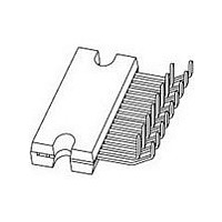
Through Hole
Pin Count
17
Package Type
DBS17P
Lead Free Status / Rohs Status
Compliant
Available stocks
Company
Part Number
Manufacturer
Quantity
Price
Company:

Part Number:
TDA8566Q
Manufacturer:
MAXIM
Quantity:
300
Part Number:
TDA8566Q
Manufacturer:
PHILIPS/飞利浦
Quantity:
20 000
Part Number:
TDA8566Q 70039AB
Manufacturer:
NXP/恩智浦
Quantity:
20 000
Company:
Part Number:
TDA8566Q/N2/S438
Manufacturer:
AELTA
Quantity:
27
Company:
Part Number:
TDA8566Q/N2S,112
Manufacturer:
IDT
Quantity:
6 792


NXP Semiconductors
7. Functional description
TDA8566_6
Product data sheet
7.1 Mode select switch (pin MODE)
7.2 Clip detection (pin CLIP)
Table 4.
The TDA8566 contains 2 identical amplifiers and can be used for BTL applications. The
gain of each amplifier is fixed at 26 dB. Special features of this device are:
Since this pin has a very low input current (< 40 A), a low-cost supply switch can be
applied. To avoid switch-on plops, it is advisable to keep the amplifier in the mute mode for
a period of
This can be realized by using a microcontroller or by using an external timing circuit as
illustrated in
When clipping occurs at one or more output stages, the dynamic distortion detector
becomes active and pin CLIP goes LOW. This information can be used to drive a sound
processor or a DC volume control to attenuate the input signal and so limit the level of
distortion. The output level of pin CLIP is independent of the number of channels that are
being clipped. The clip detection circuit is disabled in a short-circuit condition, so if a fault
condition occurs at the outputs, pin CLIP will remain at a HIGH level. The clip detection
waveforms are illustrated in
Symbol
OUT2+
PGND2
OUT2
V
MODE
DIAG
IN2+
IN2
•
•
•
•
•
•
•
•
•
P2
Mode select switch
Clip detection
Short-circuit diagnostic
Temperature pre-warning
Open-collector diagnostic outputs
Differential inputs
Standby: low supply current
Mute: input signal suppressed
Operating: normal on condition
Pin description TDA8566Q
Figure
Pin
10
11
12
13
14
15
16
17
150 ms (charging the input capacitors at pins IN1+, IN1 , IN2+ and IN2 ).
8.
Rev. 06 — 15 October 2007
Description
channel 2 output positive
power ground 2
channel 2 output negative
supply voltage 2
mode select switch input (standby/mute/operating)
short-circuit and temperature pre-warning diagnostic output
channel 2 input positive
channel 2 input negative
Figure
5.
2
…continued
40 W/2
stereo BTL car radio power amplifier
TDA8566
© NXP B.V. 2007. All rights reserved.
6 of 21
Related parts for TDA8566Q
Image
Part Number
Description
Manufacturer
Datasheet
Request
R

Part Number:
Description:
NXP Semiconductors designed the LPC2420/2460 microcontroller around a 16-bit/32-bitARM7TDMI-S CPU core with real-time debug interfaces that include both JTAG andembedded trace
Manufacturer:
NXP Semiconductors
Datasheet:

Part Number:
Description:
NXP Semiconductors designed the LPC2458 microcontroller around a 16-bit/32-bitARM7TDMI-S CPU core with real-time debug interfaces that include both JTAG andembedded trace
Manufacturer:
NXP Semiconductors
Datasheet:
Part Number:
Description:
NXP Semiconductors designed the LPC2468 microcontroller around a 16-bit/32-bitARM7TDMI-S CPU core with real-time debug interfaces that include both JTAG andembedded trace
Manufacturer:
NXP Semiconductors
Datasheet:
Part Number:
Description:
NXP Semiconductors designed the LPC2470 microcontroller, powered by theARM7TDMI-S core, to be a highly integrated microcontroller for a wide range ofapplications that require advanced communications and high quality graphic displays
Manufacturer:
NXP Semiconductors
Datasheet:
Part Number:
Description:
NXP Semiconductors designed the LPC2478 microcontroller, powered by theARM7TDMI-S core, to be a highly integrated microcontroller for a wide range ofapplications that require advanced communications and high quality graphic displays
Manufacturer:
NXP Semiconductors
Datasheet:
Part Number:
Description:
The Philips Semiconductors XA (eXtended Architecture) family of 16-bit single-chip microcontrollers is powerful enough to easily handle the requirements of high performance embedded applications, yet inexpensive enough to compete in the market for hi
Manufacturer:
NXP Semiconductors
Datasheet:
Part Number:
Description:
The XA-S3 device is a member of Philips Semiconductors? XA(eXtended Architecture) family of high performance 16-bitsingle-chip microcontrollers
Manufacturer:
NXP Semiconductors
Datasheet:

Part Number:
Description:
The NXP BlueStreak LH75401/LH75411 family consists of two low-cost 16/32-bit System-on-Chip (SoC) devices
Manufacturer:
NXP Semiconductors
Datasheet:
Part Number:
Description:
The NXP LPC3130/3131 combine an 180 MHz ARM926EJ-S CPU core, high-speed USB2
Manufacturer:
NXP Semiconductors
Datasheet:
Part Number:
Description:
The NXP LPC3141 combine a 270 MHz ARM926EJ-S CPU core, High-speed USB 2
Manufacturer:
NXP Semiconductors
Part Number:
Description:
The NXP LPC3143 combine a 270 MHz ARM926EJ-S CPU core, High-speed USB 2
Manufacturer:
NXP Semiconductors

Part Number:
Description:
The NXP LPC3152 combines an 180 MHz ARM926EJ-S CPU core, High-speed USB 2
Manufacturer:
NXP Semiconductors
Part Number:
Description:
The NXP LPC3154 combines an 180 MHz ARM926EJ-S CPU core, High-speed USB 2
Manufacturer:
NXP Semiconductors

Part Number:
Description:
Standard level N-channel enhancement mode Field-Effect Transistor (FET) in a plastic package using NXP High-Performance Automotive (HPA) TrenchMOS technology
Manufacturer:
NXP Semiconductors
Datasheet: