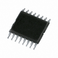
74LV4052PW,112 NXP Semiconductors, 74LV4052PW,112 Datasheet - Page 8

74LV4052PW,112
Manufacturer Part Number
74LV4052PW,112
Description
IC MUX/DEMUX DUAL 4X1 16TSSOP
Manufacturer
NXP Semiconductors
Series
74LVr
Type
Analog Multiplexerr
Datasheet
1.74LV4052DB118.pdf
(16 pages)
Specifications of 74LV4052PW,112
Function
Multiplexer/Demultiplexer
Circuit
2 x 4:1
On-state Resistance
60 Ohm
Voltage Supply Source
Single Supply
Voltage - Supply, Single/dual (±)
2.7 V ~ 3.6 V
Current - Supply
80µA
Operating Temperature
-40°C ~ 125°C
Mounting Type
Surface Mount
Package / Case
16-TSSOP (0.173", 4.40mm Width)
Multiplexer Configuration
Dual 4:1
Number Of Inputs
8
Number Of Outputs
2
Number Of Channels
2
Analog Switch On Resistance
250@1.2VOhm
Package Type
TSSOP
Power Supply Requirement
Single
Single Supply Voltage (min)
1V
Single Supply Voltage (typ)
3.3V
Single Supply Voltage (max)
6V
Dual Supply Voltage (min)
Not RequiredV
Dual Supply Voltage (typ)
Not RequiredV
Dual Supply Voltage (max)
Not RequiredV
Power Dissipation
400mW
Mounting
Surface Mount
Pin Count
16
Operating Temp Range
-40C to 125C
Operating Temperature Classification
Automotive
Lead Free Status / RoHS Status
Lead free / RoHS Compliant
Other names
74LV4052PW
74LV4052PW
935174950112
74LV4052PW
935174950112
Philips Semiconductors
1998 Jun 23
AC CHARACTERISTICS
GND = 0 V; t
NOTES:
1. Unless otherwise stated, all typical values are measured at T
2. Typical values are measured at V
SYMBOL
SYMBOL
t
t
t
t
t
t
PHL/
PHL/
PZH
PZH
PHZ
PHZ
Dual 4-channel analog multiplexer/demultiplexer
V
/t
/t
/t
/t
t
t
CC
PLH
PLH
PZL
PZL
PLZ
PLZ
6.0
4.0
2.0
(V)
– GND
Figure 5. Guaranteed operating area as a
r
0
= t
Propagation delay
V
Turn-on time
E, S
Turn-off time
E, Sn to V
f
function of the supply voltages.
is
to V
2.5ns; C
n
PARAMETER
PARAMETER
to V
g
os
2.0
OS
OS
L
= 50pF
operating area
y
4.0
CC
= 3.3 V.
6.0
3.0 to 3.6
3.0 to 3.6
3.0 to 3.6
V
SV01662
CC
V
(V)
1.2
2.0
2.7
4.5
6.0
1.2
2.0
2.7
4.5
6.0
1.2
2.0
2.7
4.5
6.0
(V)
– V
CC
CONDITION
CONDITION
EE
amb
= 25 C
8
R
R
C
C
Figure 12
Figure 12
C
C
Figures 13
Figures 13
R
R
L
L
L
L
R
R
L
OTHER
L
L
L
L
= ;
=
= 50 pF
= 50 F
L
L
and 1
and 1
and 1
= 50 pF
= 50 pF
= 1kW;
= 1kW:
= 1kW:
d 1
1kW
MIN
–40 to +85 C
TYP
190
125
36
26
25
5
65
48
32
25
43
33
23
18
9
6
4
3
2
2
2
1
LIMITS
MAX
121
17
13
10
89
71
60
46
80
59
48
41
32
9
7
–40 to +125 C
MIN
Product specification
74LV4052
MAX
146
108
20
15
12
10
86
73
56
95
71
57
49
38
8
UNIT
UNIT
ns
ns
ns
ns
ns
ns


