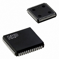
SC28C94A1A,518 NXP Semiconductors, SC28C94A1A,518 Datasheet - Page 20

SC28C94A1A,518
Manufacturer Part Number
SC28C94A1A,518
Description
IC UART QUAD W/FIFO 52-PLCC
Manufacturer
NXP Semiconductors
Datasheet
1.SC28C94A1A518.pdf
(39 pages)
Specifications of SC28C94A1A,518
Features
False-start Bit Detection
Number Of Channels
4, QUART
Fifo's
8 Byte
Voltage - Supply
5V
With Auto Flow Control
Yes
With False Start Bit Detection
Yes
With Modem Control
Yes
With Cmos
Yes
Mounting Type
Surface Mount
Package / Case
52-PLCC
Lead Free Status / RoHS Status
Lead free / RoHS Compliant
Other names
568-1114-2
935262534518
SC28C94A1A-T
935262534518
SC28C94A1A-T
Available stocks
Company
Part Number
Manufacturer
Quantity
Price
Company:
Part Number:
SC28C94A1A,518
Manufacturer:
Maxim
Quantity:
21
Company:
Part Number:
SC28C94A1A,518
Manufacturer:
NXP Semiconductors
Quantity:
10 000
Philips Semiconductors
In the counter mode, the C/T counts down the number of pulses
loaded in CTUR and CTLR by the CPU. Counting begins upon
receipt of a start counter command. Upon reaching the terminal
count H‘0000’, the counter ready interrupt bit (ISR[3]) is set. The
counter rolls over to 65535 and continues counting until stopped by
the CPU. If I/O is programmed to be the output of the C/T, the output
remains High until the terminal count is reached, at which time it
goes Low. The output returns to the High state and ISR[3] is cleared
when the counter is stopped by a stop counter command. The CPU
may change the values of CTUR and CTLR at any time, but the new
count becomes effective only on the next start counter command. If
new values have not been loaded, the previous values are
preserved and used for the next count cycle.
In the counter mode, the current value of the upper and lower eight
bits of the counter (CTU, CTL) may be read by the CPU. It is
recommended that the counter be stopped when reading to prevent
potential problems which may occur if a carry from the lower eight
bits to the upper eight bits occurs between the times that both
halves of the counter is read. However, note that a subsequent start
counter command will cause the counter to begin a new count cycle
using the values in CTUR and CTLR.
I/O LOGIC
The QUART has four I/O pins for each channel. These pins may be
individually programmed as an input or output under control of the
2006 Aug 09
Quad universal asynchronous receiver/transmitter (QUART)
20
I/OPCR (I/O Port Control Register). Functions which may use the
I/O pins as inputs (Rx or Tx external clock, for example) are always
sensitive to the signal on the I/O pin regardless of it being
programmed as an input or an output. For example if I/O1a was
programmed to output the RxC1X clock and the Counter/Timer was
programmed to use I/O pin as its clock input the result would be the
Counter/Timer being clocked by the RxC1X clock.
The 16 I/O ports are accessed and/or controlled by five (5) registers:
IPR, ACR, I/OPCR, IPCR, OPR. They are shown in Table 8 of this
document. Each UART has four pins. Two of these pins have
“Change of State Detectors” (COS). These detectors set
whenever the pin to which they are attached changes state. (1 to 0
or 0 to 1) The “Change of State Detectors” are enabled via the
ACR. When enabled the COS devices may generate interrupts via
the IMR and IPCR registers. Note that when the COS interrupt is
enabled that any one or more of the four COS bits in the IPCR will
enable the COS bidding. Each of the channel’s four I/O lines are
configured as inputs on reset.
The Change of State detectors sample the I/O pins at the rate of the
38.4KHz clock. A change on the pin will be required to be stable for
at least 26.04 s and as much as 52.08 s for the COS detectors to
confirm a change. Note that changes in the X1/clock frequency will
effect this stability requirement.
COS detectors are reset by a read of the IPCR.
SC28C94
Product data sheet


