MAX3107ETG+ Maxim Integrated Products, MAX3107ETG+ Datasheet - Page 12
MAX3107ETG+
Manufacturer Part Number
MAX3107ETG+
Description
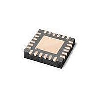
IC UART SPI/I2C 128 FIFO 24TQFN
Manufacturer
Maxim Integrated Products
Datasheet
1.MAX3107EAG.pdf
(52 pages)
Specifications of MAX3107ETG+
Features
Internal Oscillators
Number Of Channels
4, QUART
Fifo's
128 Byte
Protocol
RS232, RS485
Voltage - Supply
2.35 V ~ 3.6 V
With Auto Flow Control
Yes
With Irda Encoder/decoder
Yes
With False Start Bit Detection
Yes
Mounting Type
Surface Mount
Package / Case
24-TQFN Exposed Pad
Data Rate
24 Mbps
Supply Voltage (max)
3.3 V
Supply Voltage (min)
2.35 V
Supply Current
0.64 mA
Maximum Operating Temperature
+ 85 C
Minimum Operating Temperature
- 40 C
Mounting Style
SMD/SMT
No. Of Channels
1
Uart Features
128-Word Transmit / Receive FIFO, Half-Duplex Echo Suppression, Shutdown And Autosleep Modes
Supply Voltage Range
2.35V To 3.6V
Rohs Compliant
Yes
Lead Free Status / RoHS Status
Lead free / RoHS Compliant


SPI/I
and Internal Oscillator
12
TQFN-EP
_____________________________________________________________________________________
1
2
3
4
5
6
PIN
2
TOP VIEW
C UART with 128-Word FIFOs
SSOP
*CONNECT EP TO AGND.
4
5
6
7
8
9
AGND
XOUT
V
XIN
EXT
TX
V
A
19
20
21
22
23
24
DOUT/SDA
SCLK/SCL
18
+
1
I2C/SPI
LDOEN
(3.5mm × 3.5mm)
NAME
CS/A0
V
17
2
18
MAX3107
TQFN
16
3
15
4
Internal 1.8V LDO Output and 1.8V Logic Supply Input. Bypass V
ceramic capacitor to DGND.
SPI or Active-Low I
low to enable I
LDO Enable Input. Drive LDOEN high to enable the internal 1.8V LDO. Drive LDOEN
low to disable the internal LDO. When LDO is low, V
nal voltage source.
Serial-Data Output. When I2C/SPI is high, DOUT/SDA functions as the DOUT SPI
serial-data output. When I2C/SPI is low, DOUT/SDA functions as the SDA I
data input/output.
Serial-Clock Input. When I2C/SPI is high, SCLK/SCL functions as the SCLK SPI
serial-clock input (up to 26MHz). When I2C/SPI is low, SCLK/SCL functions as the
SCL I
Active-Low Chip-Select and Address 0 Input. When I2C/SPI is high, CS/A0 functions
as the CS SPI active-low chip select. When I2C/SPI is low, CS/A0 functions as the
A0 I
14
5
*EP
2
13
6
C device address programming input. Connect CS/A0 to DGND or V
2
C serial-clock input (up to 400kHz).
12
11
10
9
8
7
GPIO0
DGND
V
RST
IRQ
DIN/A1
L
2
C.
2
C Selector Input. Drive I2C/SPI high to enable SPI. Drive I2C/SPI
DOUT/SDA
SCLK/SCL
I2C/SPI
LDOEN
DIN/A1
CS/A0
AGND
RST
XIN
V
IRQ
V
18
A
FUNCTION
10
11
12
1
2
3
4
5
6
7
8
9
+
MAX3107
SSOP
18
Pin Configurations
can be supplied by an exter-
Pin Descriptions
24
23
22
21
20
19
18
17
16
15
14
13
XOUT
V
TX
RX
CTS
GPIO3
GPIO2
GPIO1
GPIO0
DGND
V
RTS/CLKOUT
EXT
L
18
with a 0.1FF
L
2
.
C serial-
Related parts for MAX3107ETG+
Image
Part Number
Description
Manufacturer
Datasheet
Request
R

Part Number:
Description:
MAX7528KCWPMaxim Integrated Products [CMOS Dual 8-Bit Buffered Multiplying DACs]
Manufacturer:
Maxim Integrated Products
Datasheet:
Part Number:
Description:
Single +5V, fully integrated, 1.25Gbps laser diode driver.
Manufacturer:
Maxim Integrated Products
Datasheet:
Part Number:
Description:
Single +5V, fully integrated, 155Mbps laser diode driver.
Manufacturer:
Maxim Integrated Products
Datasheet:
Part Number:
Description:
VRD11/VRD10, K8 Rev F 2/3/4-Phase PWM Controllers with Integrated Dual MOSFET Drivers
Manufacturer:
Maxim Integrated Products
Datasheet:
Part Number:
Description:
Highly Integrated Level 2 SMBus Battery Chargers
Manufacturer:
Maxim Integrated Products
Datasheet:
Part Number:
Description:
Current Monitor and Accumulator with Integrated Sense Resistor; ; Temperature Range: -40°C to +85°C
Manufacturer:
Maxim Integrated Products
Part Number:
Description:
TSSOP 14/A�/RS-485 Transceivers with Integrated 100O/120O Termination Resis
Manufacturer:
Maxim Integrated Products
Part Number:
Description:
TSSOP 14/A�/RS-485 Transceivers with Integrated 100O/120O Termination Resis
Manufacturer:
Maxim Integrated Products
Part Number:
Description:
QFN 16/A�/AC-DC and DC-DC Peak-Current-Mode Converters with Integrated Step
Manufacturer:
Maxim Integrated Products
Part Number:
Description:
TDFN/A/65V, 1A, 600KHZ, SYNCHRONOUS STEP-DOWN REGULATOR WITH INTEGRATED SWI
Manufacturer:
Maxim Integrated Products
Part Number:
Description:
Integrated Temperature Controller f
Manufacturer:
Maxim Integrated Products
Part Number:
Description:
SOT23-6/I�/45MHz to 650MHz, Integrated IF VCOs with Differential Output
Manufacturer:
Maxim Integrated Products
Part Number:
Description:
SOT23-6/I�/45MHz to 650MHz, Integrated IF VCOs with Differential Output
Manufacturer:
Maxim Integrated Products
Part Number:
Description:
EVALUATION KIT/2.4GHZ TO 2.5GHZ 802.11G/B RF TRANSCEIVER WITH INTEGRATED PA
Manufacturer:
Maxim Integrated Products