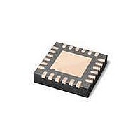
MAX3107ETG+ Maxim Integrated Products, MAX3107ETG+ Datasheet - Page 31

MAX3107ETG+
Manufacturer Part Number
MAX3107ETG+
Description
IC UART SPI/I2C 128 FIFO 24TQFN
Manufacturer
Maxim Integrated Products
Datasheet
1.MAX3107EAG.pdf
(52 pages)
Specifications of MAX3107ETG+
Features
Internal Oscillators
Number Of Channels
4, QUART
Fifo's
128 Byte
Protocol
RS232, RS485
Voltage - Supply
2.35 V ~ 3.6 V
With Auto Flow Control
Yes
With Irda Encoder/decoder
Yes
With False Start Bit Detection
Yes
Mounting Type
Surface Mount
Package / Case
24-TQFN Exposed Pad
Data Rate
24 Mbps
Supply Voltage (max)
3.3 V
Supply Voltage (min)
2.35 V
Supply Current
0.64 mA
Maximum Operating Temperature
+ 85 C
Minimum Operating Temperature
- 40 C
Mounting Style
SMD/SMT
No. Of Channels
1
Uart Features
128-Word Transmit / Receive FIFO, Half-Duplex Echo Suppression, Shutdown And Autosleep Modes
Supply Voltage Range
2.35V To 3.6V
Rohs Compliant
Yes
Lead Free Status / RoHS Status
Lead free / RoHS Compliant
MODE1 Register
Bit 7: IRQSel
Depending on the logic level of the IRQSel bit, IRQ has different meanings. After a hardware or software (MODE2[0])
reset, the IRQSel bit is set low and after a short delay, the IRQ output signals the end of the MAX3107’s power-up
sequence. The IRQ is low during power-up and transitions to high when the MAX3107 is ready to be programmed.
IRQSel can then be set high. In this case, IRQ becomes a regular interrupt output that signals pending interrupts, as
indicated in the ISR. Details of the IRQSel are described in the Power-Up and IRQ section.
Bit 6: AutoSleep
Set the AutoSleep bit high to set the MAX3107 to automatically enter low-power sleep mode after a period of no activ-
ity (see the Autosleep Mode section). A STSInt[6]: SleepInt interrupt is generated when the MAX3107 goes to sleep or
wakes up.
Bit 5: ForcedSleep
Set the ForcedSleep bit high to force the MAX3107 into low-power sleep mode (see the Sleep Mode section). The cur-
rent sleep or wake state can be read out through this ForcedSleep bit, even when the UART is in sleep mode.
Bit 4: TrnscvCtrl
This bit enables the automatic transceiver direction control. Set TrnscvCtrl high so that RTS/CLKOUT automatically
controls the transceiver’s transmit/receive enable/disable inputs. Setting TrnscvCtrl high sets RTS/CLKOUT low so
that the transceiver is in receive mode. When the TxFIFO contains data available for transmission, the auto direction
control sets RTS/CLKOUT high before the transmitter sends out the data. When the transmitter is empty, RTS/CLKOUT
is automatically forced low again.
Setup and hold times of RTS/CLKOUT with respect to the TX output can be defined through the HDplxDelay register.
A transmitter empty interrupt ISR[5] is generated when the transmitter is empty.
Bit 3: RTSHiZ
Set the RTSHiZ bit high to three-state RTS/CLKOUT.
Bit 2: TxHiZ
Set the TxHiz bit high to three-state the TX output.
Bit 1: TxDisabl
Set the TxDisabl bit high to disable transmission. If the TxDisabl bit is set high during transmission, the transmitter com-
pletes sending out the current character and then ceases transmission. Data still present in the transmit FIFO remains
in the TxFIFO. The TX output is set to logic-high after transmission.
Bit 0: RxDisabl
Set the RxDisabl bit high to disable the receiver so that the receiver stops receiving data. All data present in the receive
FIFO remains in the RxFIFO.
ADDRESS:
MODE:
RESET
NAME
BIT
IRQSel
______________________________________________________________________________________
7
0
0x09
R/W
AutoSleep
SPI/I
6
0
ForcedSleep
2
5
0
C UART with 128-Word FIFOs
TrnscvCtrl
4
0
and Internal Oscillator
RTSHiZ
3
0
TxHiZ
2
0
TxDisabl
1
0
RxDisabl
0
0
31


