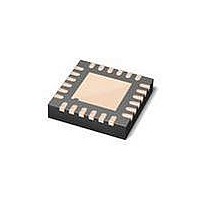
MAX3107ETG+ Maxim Integrated Products, MAX3107ETG+ Datasheet - Page 25

MAX3107ETG+
Manufacturer Part Number
MAX3107ETG+
Description
IC UART SPI/I2C 128 FIFO 24TQFN
Manufacturer
Maxim Integrated Products
Datasheet
1.MAX3107EAG.pdf
(52 pages)
Specifications of MAX3107ETG+
Features
Internal Oscillators
Number Of Channels
4, QUART
Fifo's
128 Byte
Protocol
RS232, RS485
Voltage - Supply
2.35 V ~ 3.6 V
With Auto Flow Control
Yes
With Irda Encoder/decoder
Yes
With False Start Bit Detection
Yes
Mounting Type
Surface Mount
Package / Case
24-TQFN Exposed Pad
Data Rate
24 Mbps
Supply Voltage (max)
3.3 V
Supply Voltage (min)
2.35 V
Supply Current
0.64 mA
Maximum Operating Temperature
+ 85 C
Minimum Operating Temperature
- 40 C
Mounting Style
SMD/SMT
No. Of Channels
1
Uart Features
128-Word Transmit / Receive FIFO, Half-Duplex Echo Suppression, Shutdown And Autosleep Modes
Supply Voltage Range
2.35V To 3.6V
Rohs Compliant
Yes
Lead Free Status / RoHS Status
Lead free / RoHS Compliant
Bit 0: LSRErrlEn
The LSRErrIEn bit enables IRQ interrupt generation when the LSRErrInt interrupt bit is set in the ISR[0]. Set LSRErrIEn
low to disable IRQ generation from LSRErrInt.
ISR—Interrupt Status Register
The ISR provides an overview of all interrupts generated in the MAX3107. These interrupts are cleared on reading the
ISR. When the MAX3107 is operated in polled mode, the ISR can be polled to establish the UART’s status. In interrupt-
driven mode, IRQ interrupts are enabled through the appropriate IRQEn bits. The ISR contents give direct information
on the cause for the interrupt or point to other registers that contain more detailed information.
Bit 7: CTSInt
The CTSInt is set when a logic state transition occurs at the CTS input. This bit is cleared after ISR is read. The current
logic state of the CTS input can be read out through the LSR[7]: CTSbit.
Bit 6: RxEmptyInt
The RxEmptyInt is set when the receive FIFO is empty. This bit is cleared after ISR is read. Its meaning can be inverted
by setting the MODE2[3]: RxEmtyInv bit.
Bit 5: TxEmptyInt
The TxEmptyInt bit is set when the transmit FIFO is empty. This bit is cleared once ISR is read.
Bit 4: TFifoTriglnt
The TFifoTrigInt bit is set when the number of characters in the transmit FIFO is equal to or greater than the transmit
FIFO trigger level defined in FIFOTrgLvl[3:0]. TFifoTrigInt is cleared when the transmit FIFO level falls below the trigger
level or after the ISR is read. It can be used as a warning that the transmit FIFO is nearing overflow.
Bit 3: RFifoTriglnt
The RFifoTrigInt bit is set when the receive FIFO fill level reaches the receive FIFO trigger level, as defined in the
FIFOTrgLvl[7:4]. This can be used as an indication that the receive FIFO is nearing overrun. It can also be used to
report that a known number of words are available which can be read out in one block. The meaning of RFifoTrigInt
can be inverted through MODE2[2]. RFifoTrigInt is cleared when ISR is read.
Bit 2: STSInt
The STSInt bit is set high when any bit in the STSInt register that is enabled through a STSIntEn bit is high. The STSInt
bit is cleared on reading ISR.
Bit 1: SpCharlnt
The SpCharInt bit is set high when a special character is received, a line BREAK is detected, or an address character is
received in multidrop mode. The cause for the SpCharInt interrupt can be read from the SpclCharInt register, if enabled
through the SpclChrIntEn bits. The SpCharInt interrupt is cleared when the ISR is read.
Bit 0: LSRErrlnt
The LSRErrInt bit is set high when any LSR bits, which are enabled through the LSRIntEn, are set. This bit is cleared
after the ISR is read.
ADDRESS:
MODE:
RESET
NAME
BIT
CTSInt
______________________________________________________________________________________
7
0
0x02
COR
RxEmptyInt
SPI/I
6
1
TxEmptyInt
2
5
1
C UART with 128-Word FIFOs
TFifoTrigInt
4
0
and Internal Oscillator
RFifoTrigInt
3
0
STSInt
2
0
SpCharInt
1
0
LSRErrInt
0
0
25


