TDA2052V STMicroelectronics, TDA2052V Datasheet - Page 3
TDA2052V
Manufacturer Part Number
TDA2052V
Description
IC AMP AUDIO PWR HIFI HEPTAWATT7
Manufacturer
STMicroelectronics
Type
Class ABr
Datasheet
1.TDA2052V.pdf
(14 pages)
Specifications of TDA2052V
Output Type
1-Channel (Mono)
Max Output Power X Channels @ Load
40W x 1 @ 4 Ohm
Voltage - Supply
±6 V ~ 25 V
Features
Mute, Short-Circuit and Thermal Protection, Standby
Mounting Type
Through Hole
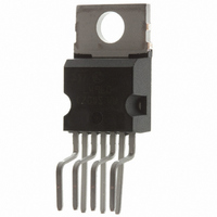
Package / Case
Heptawatt-7 (Vertical, Bent and Staggered Leads)
Amplifier Class
AB
No. Of Channels
1
Load Impedance
8ohm
Operating Temperature Range
0°C To +70°C
Amplifier Case Style
Heptawatt H
No. Of Pins
7
Svhc
No SVHC (15-Dec-2010)
Base Number
2052
Rohs Compliant
Yes
Product
Class-AB
Output Power
40 W
Available Set Gain
80 dB
Thd Plus Noise
0.1 %
Supply Current
6 A
Maximum Power Dissipation
30000 mW
Maximum Operating Temperature
+ 70 C
Mounting Style
Through Hole
Audio Load Resistance
8 Ohms
Dual Supply Voltage
+/- 9 V, +/- 12 V, +/- 15 V, +/- 18 V, +/- 24 V
Input Bias Current (max)
0.5 uA
Input Offset Voltage
15 mV
Input Signal Type
Single
Minimum Operating Temperature
0 C
Output Signal Type
Single
Supply Type
Dual
Supply Voltage Range
± 6V To ± 25V
Thd + N
0.1% @ 20W, 8ohm, VS=± 22V
Lead Free Status / RoHS Status
Lead free / RoHS Compliant
Other names
497-3955-5
Available stocks
Company
Part Number
Manufacturer
Quantity
Price


THERMAL DATA
ELECTRICAL CHARACTERISTICS (Refer to the test circuit, G
25 C, unless otherwise specified.)
MUTE/STAND-BY FUNCTION (Ref. –V
Note (*):
MUSIC POWER CONCEPT
MUSIC POWER is ( according to the IEC clauses n.268-3 of Jan 83) the maximal power which the amplifier is capable of producing across the
rated load resistance (regardless of non linearity) 1 sec after the application of a sinusoidal input signal of frequency 1KHz.
According to this definition our method of measurement comprises the following steps:
1) Set the voltage supply at the maximum operating value -10%
2) Apply a input signal in the form of a 1KHz tone burst of 1 sec duration; the repetition period of the signal pulses is > 60 sec
3) The output voltage is measured 1 sec from the start of the pulse
4) Increase the input voltage until the output signal show a THD = 10%
5) The music power is then V
The target of this method is to avoid excessive dissipation in the amplifier.
Symbol
ATT
R
Symbol
VT
VT
I
q ST-BY
th j-case
SVR
V
I
I
SR
P
P
G
V
T
e
pin3
R
ST-BY
OS
I
I
d
PLAY
OS
ST-BY
q
b
O
O
N
S
S
V
i
Thermal Resistance Junction-case
Supply Range
Total Quiescent Current
Input Bias Current
Input Offset Voltage
Input Offset Current
Music Output Power
IEC268-3 Rules (*)
Output Power (continuous RMS)
Total Harmonic Distortion
Slew Rate
Open Loop Voltage Gain
Total Input Noise
Input Resistance
Supply Voltage Rejection
Thermal Shutdown
Stand-by - Threshold
Play Threshold
Quiescent Current @ Stand-by
Stand-by Attenuation
Pin 3 Current @ Stand-by
2
out
Parameter
/R1
,
where V
out
is the output voltage measured in the condition of point 4) and R1 is the rated load impedance
S
)
Description
V
V
d = 10%
RL = 4
R
V
d = 1%
R
R
V
R
P
f = 100Hz to 15KHz
V
P
f = 100Hz to 15KHz
A Curve
f = 20Hz to 20KHz
f = 100Hz, V
V
d = 10%, t = 1s
S
S
S
S
O
S
O
pin 3
L
L
L
L
= 8
= 4
= 8
= 4
= +22V
= + 22.5, R
= +22V, R
= +22V, R
+ 22V, R
= 0.1 to 20W;
= 0.1 to 20W;
= 0.5V
Test Condition
L
ripple
L
L
= 8
L
= 8
= 8
= 4 ,
= 1V
RMS
V
= 32dB; V
Min.
500
+6
20
50
35
30
40
70
3
1
S
Max
+ 18V; f = 1KHz; T
Typ.
145
0.1
0.1
1.8
2.7
40
60
40
22
33
32
17
28
80
50
90
–1
5
2
3
1
Value
2.5
Max.
+200
+0.5
+25
+15
+10
0.7
0.5
70
10
4
3
TDA2052
Unit
Unit
V/ s
C/W
mA
mV
K
mA
amb
nA
dB
dB
dB
W
W
W
W
W
W
W
%
%
V
V
V
C
A
V
V
A
3/14
=
Related parts for TDA2052V
Image
Part Number
Description
Manufacturer
Datasheet
Request
R

Part Number:
Description:
STMicroelectronics [RIPPLE-CARRY BINARY COUNTER/DIVIDERS]
Manufacturer:
STMicroelectronics
Datasheet:
Part Number:
Description:
STMicroelectronics [LIQUID-CRYSTAL DISPLAY DRIVERS]
Manufacturer:
STMicroelectronics
Datasheet:

Part Number:
Description:
BOARD EVAL FOR MEMS SENSORS
Manufacturer:
STMicroelectronics
Datasheet:
Part Number:
Description:
NPN TRANSISTOR POWER MODULE
Manufacturer:
STMicroelectronics
Datasheet:
Part Number:
Description:
TURBOSWITCH ULTRA-FAST HIGH VOLTAGE DIODE
Manufacturer:
STMicroelectronics
Datasheet:
Part Number:
Description:
Manufacturer:
STMicroelectronics
Datasheet:
Part Number:
Description:
DIODE / SCR MODULE
Manufacturer:
STMicroelectronics
Datasheet:
Part Number:
Description:
DIODE / SCR MODULE
Manufacturer:
STMicroelectronics
Datasheet:
Part Number:
Description:
Search -----> STE16N100
Manufacturer:
STMicroelectronics
Datasheet:
Part Number:
Description:
Search ---> STE53NA50
Manufacturer:
STMicroelectronics
Datasheet:
Part Number:
Description:
NPN Transistor Power Module
Manufacturer:
STMicroelectronics
Datasheet:
Part Number:
Description:
DIODE / SCR MODULE
Manufacturer:
STMicroelectronics
Datasheet: