TDA2052V STMicroelectronics, TDA2052V Datasheet - Page 4
TDA2052V
Manufacturer Part Number
TDA2052V
Description
IC AMP AUDIO PWR HIFI HEPTAWATT7
Manufacturer
STMicroelectronics
Type
Class ABr
Datasheet
1.TDA2052V.pdf
(14 pages)
Specifications of TDA2052V
Output Type
1-Channel (Mono)
Max Output Power X Channels @ Load
40W x 1 @ 4 Ohm
Voltage - Supply
±6 V ~ 25 V
Features
Mute, Short-Circuit and Thermal Protection, Standby
Mounting Type
Through Hole
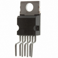
Package / Case
Heptawatt-7 (Vertical, Bent and Staggered Leads)
Amplifier Class
AB
No. Of Channels
1
Load Impedance
8ohm
Operating Temperature Range
0°C To +70°C
Amplifier Case Style
Heptawatt H
No. Of Pins
7
Svhc
No SVHC (15-Dec-2010)
Base Number
2052
Rohs Compliant
Yes
Product
Class-AB
Output Power
40 W
Available Set Gain
80 dB
Thd Plus Noise
0.1 %
Supply Current
6 A
Maximum Power Dissipation
30000 mW
Maximum Operating Temperature
+ 70 C
Mounting Style
Through Hole
Audio Load Resistance
8 Ohms
Dual Supply Voltage
+/- 9 V, +/- 12 V, +/- 15 V, +/- 18 V, +/- 24 V
Input Bias Current (max)
0.5 uA
Input Offset Voltage
15 mV
Input Signal Type
Single
Minimum Operating Temperature
0 C
Output Signal Type
Single
Supply Type
Dual
Supply Voltage Range
± 6V To ± 25V
Thd + N
0.1% @ 20W, 8ohm, VS=± 22V
Lead Free Status / RoHS Status
Lead free / RoHS Compliant
Other names
497-3955-5
Available stocks
Company
Part Number
Manufacturer
Quantity
Price


TDA2052
APPLICATIONS SUGGESTIONS (See Test and Application Circuit)
The recommended values of the external components are those shown on the application circuit. Differ-
ent values can be used; the following table can help the designer.
(*) R1 = R3 = R4 for POP optimization
(**) Closed Loop Gain has to be
TYPICAL CHARACTERISTICS
Figure 1: Output Power vs. Supply Voltage
4/14
Comp.
C5, C6
R1
R2
R3
R4
R5
R6
C1
C2
C3
C4
22K (*)
22K (*)
22K (*)
0.100 F
1000 F
22K
Value
560
10 F
10 F
4.7
1 F
30dB
Input Impedance
Closed Loop Gain set to
32dB (**)
Input Impedance @ Mute
Stand-by Time Constant
Frequency Stability
Input DC Decoupling
Feedback DC Decoupling
Stand-by Time Constant
Frequency Stability
Supply Voltage Bypass
Purpose
Figure 2: Distortion vs. Output Power
Increase of Input
Impedance
Decrease of Gain
Increase of Gain
Danger of oscillations
Larger Than
Decrease of Input
Impedance
Increase of Gain
Decrease of Gain
Danger of oscillations
Higher Low-frequency
cut-off
Higher Low-frequency
cut-off
Danger of Oscillations
Smaller Than
Related parts for TDA2052V
Image
Part Number
Description
Manufacturer
Datasheet
Request
R

Part Number:
Description:
STMicroelectronics [RIPPLE-CARRY BINARY COUNTER/DIVIDERS]
Manufacturer:
STMicroelectronics
Datasheet:
Part Number:
Description:
STMicroelectronics [LIQUID-CRYSTAL DISPLAY DRIVERS]
Manufacturer:
STMicroelectronics
Datasheet:

Part Number:
Description:
BOARD EVAL FOR MEMS SENSORS
Manufacturer:
STMicroelectronics
Datasheet:
Part Number:
Description:
NPN TRANSISTOR POWER MODULE
Manufacturer:
STMicroelectronics
Datasheet:
Part Number:
Description:
TURBOSWITCH ULTRA-FAST HIGH VOLTAGE DIODE
Manufacturer:
STMicroelectronics
Datasheet:
Part Number:
Description:
Manufacturer:
STMicroelectronics
Datasheet:
Part Number:
Description:
DIODE / SCR MODULE
Manufacturer:
STMicroelectronics
Datasheet:
Part Number:
Description:
DIODE / SCR MODULE
Manufacturer:
STMicroelectronics
Datasheet:
Part Number:
Description:
Search -----> STE16N100
Manufacturer:
STMicroelectronics
Datasheet:
Part Number:
Description:
Search ---> STE53NA50
Manufacturer:
STMicroelectronics
Datasheet:
Part Number:
Description:
NPN Transistor Power Module
Manufacturer:
STMicroelectronics
Datasheet:
Part Number:
Description:
DIODE / SCR MODULE
Manufacturer:
STMicroelectronics
Datasheet: