TDA2052V STMicroelectronics, TDA2052V Datasheet - Page 9
TDA2052V
Manufacturer Part Number
TDA2052V
Description
IC AMP AUDIO PWR HIFI HEPTAWATT7
Manufacturer
STMicroelectronics
Type
Class ABr
Datasheet
1.TDA2052V.pdf
(14 pages)
Specifications of TDA2052V
Output Type
1-Channel (Mono)
Max Output Power X Channels @ Load
40W x 1 @ 4 Ohm
Voltage - Supply
±6 V ~ 25 V
Features
Mute, Short-Circuit and Thermal Protection, Standby
Mounting Type
Through Hole
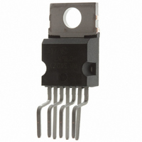
Package / Case
Heptawatt-7 (Vertical, Bent and Staggered Leads)
Amplifier Class
AB
No. Of Channels
1
Load Impedance
8ohm
Operating Temperature Range
0°C To +70°C
Amplifier Case Style
Heptawatt H
No. Of Pins
7
Svhc
No SVHC (15-Dec-2010)
Base Number
2052
Rohs Compliant
Yes
Product
Class-AB
Output Power
40 W
Available Set Gain
80 dB
Thd Plus Noise
0.1 %
Supply Current
6 A
Maximum Power Dissipation
30000 mW
Maximum Operating Temperature
+ 70 C
Mounting Style
Through Hole
Audio Load Resistance
8 Ohms
Dual Supply Voltage
+/- 9 V, +/- 12 V, +/- 15 V, +/- 18 V, +/- 24 V
Input Bias Current (max)
0.5 uA
Input Offset Voltage
15 mV
Input Signal Type
Single
Minimum Operating Temperature
0 C
Output Signal Type
Single
Supply Type
Dual
Supply Voltage Range
± 6V To ± 25V
Thd + N
0.1% @ 20W, 8ohm, VS=± 22V
Lead Free Status / RoHS Status
Lead free / RoHS Compliant
Other names
497-3955-5
Available stocks
Company
Part Number
Manufacturer
Quantity
Price


SHORT-CIRCUIT PROTECTION
The TDA 2052 has an original circuit which pro-
tects the device during accidental short-circuit be-
tween output and GND / -Vs / +Vs, taking it in
STAND-BY mode, so limiting also dangerous DC
current flowing throught the loudspeaker.
If a short-circuit or an overload dangerous for the
final transistors are detected, the concerned SOA
circuit sends out a signal to the latching circuit
(with a 10 s delay time that prevents fast random
spikes from inadvertently shutting the amplifier
off) which makes Q
Diagram). Q
the A point turning the final stage off while Q
short-circuits to ground the external capacitor
driving the pin 3 (Mute/Stand-by) towards zero
potential.
Only when the pin 3 voltage becomes lower than
1V, the latching circuit is allowed to reset itself
and restart the amplifier, provided that the short-
circuit condition has been removed. In fact, a win-
dow comparator is present at the output and it is
aimed at preventing the amplifier from restarting if
the output voltage is lower than 0.35 Total Supply
Voltage or higher than 0.65 Total Supply Voltage.
If the output voltage lies between these two
thresholds, one may reasonably suppose the
short-circuit has been removed and the amplifier
may start operating again.
The PLAY/MUTE/STAND-BY function pin (pin 3)
is both ground- and positive supply-compatible
and can be interfaced by means of the R
either to a TTL or CMOS output ( -Processor) or
to a specific application circuit.
The R
ing this pin directly to a low output impedance
driver such as TTL gate would prevent the correct
operation during a short-circuit. Actually a final
stage overload turns on the protection latching
circuit that makes Q
under 0.8 V. Since the maximum current this pin
can stand is 3 mA, one must make sure the fol-
lowing condition is met:
that yields: R
In order to prevent pop-on and -off transients, it is
advisable to calculate the C
way that the STAND-BY/MUTE and MUTE/PLAY
threshold crossing slope (positive at the turn-on
and vice-versa) is less than 100 V/sec.
5
, C
3
net is fundamental, because connect-
1
immediately short-circuits to ground
5, min
R
5
= 1.5 K
1
2
try to drive the pin 3 voltage
and Q
V
A
3mA
0.7V
2
3
with V
saturate (see Block
, R
5
A
net in such a
=5V.
5
, C
3
net
2
THERMAL PROTECTION
The thermal protection operates on the 125 A
current generator, linearly decreasing its value
from 90 C on. By doing this, the A voltage slowly
decreases thus switching the amplifier first to
MUTE (at 145 C) and then to STAND-BY
(155 C).
Figure 16: Thermal Protection Block Diagram
The maximum allowable power dissipation de-
pends on the size of the external heatsink (ther-
mal resistance case-ambient); figure 17 shows
the dissipable power as a function of ambient
temperature for different thermal resistance.
Figure 17: Maximum Allowable Power Dissipa-
tion vs. Ambient Temperature.
TDA2052
9/14
Related parts for TDA2052V
Image
Part Number
Description
Manufacturer
Datasheet
Request
R

Part Number:
Description:
STMicroelectronics [RIPPLE-CARRY BINARY COUNTER/DIVIDERS]
Manufacturer:
STMicroelectronics
Datasheet:
Part Number:
Description:
STMicroelectronics [LIQUID-CRYSTAL DISPLAY DRIVERS]
Manufacturer:
STMicroelectronics
Datasheet:

Part Number:
Description:
BOARD EVAL FOR MEMS SENSORS
Manufacturer:
STMicroelectronics
Datasheet:
Part Number:
Description:
NPN TRANSISTOR POWER MODULE
Manufacturer:
STMicroelectronics
Datasheet:
Part Number:
Description:
TURBOSWITCH ULTRA-FAST HIGH VOLTAGE DIODE
Manufacturer:
STMicroelectronics
Datasheet:
Part Number:
Description:
Manufacturer:
STMicroelectronics
Datasheet:
Part Number:
Description:
DIODE / SCR MODULE
Manufacturer:
STMicroelectronics
Datasheet:
Part Number:
Description:
DIODE / SCR MODULE
Manufacturer:
STMicroelectronics
Datasheet:
Part Number:
Description:
Search -----> STE16N100
Manufacturer:
STMicroelectronics
Datasheet:
Part Number:
Description:
Search ---> STE53NA50
Manufacturer:
STMicroelectronics
Datasheet:
Part Number:
Description:
NPN Transistor Power Module
Manufacturer:
STMicroelectronics
Datasheet:
Part Number:
Description:
DIODE / SCR MODULE
Manufacturer:
STMicroelectronics
Datasheet: