LMV1088RL/NOPB National Semiconductor, LMV1088RL/NOPB Datasheet - Page 20
LMV1088RL/NOPB
Manufacturer Part Number
LMV1088RL/NOPB
Description
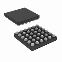
IC AMP AUDIO MONO AB MIC 36USMD
Manufacturer
National Semiconductor
Series
PowerWise®r
Type
Class ABr
Datasheet
1.LMV1088RLNOPB.pdf
(26 pages)
Specifications of LMV1088RL/NOPB
Output Type
1-Channel (Mono)
Voltage - Supply
2.7 V ~ 5.5 V
Features
Differential Inputs, I²C, Microphone, Mute
Mounting Type
Surface Mount
Package / Case
36-MicroSMDxt
Amplifier Class
AB
No. Of Channels
2
Supply Voltage Range
2.7V To 5.5V
Load Impedance
10kohm
Operating Temperature Range
-40°C To +85°C
Amplifier Case Style
SMD
No. Of Pins
36
Rohs Compliant
Yes
Lead Free Status / RoHS Status
Lead free / RoHS Compliant
Max Output Power X Channels @ Load
-
Other names
LMV1088RLTR


www.national.com
Manual Calibration
You can manually program the gain of the two mic inputs on
the LMV1088 using the I
trol bits for I
This can be easily done by doing the following:
powering up.
settings.
O<3:0> control the two mics at 3kHz.
the Mic1 gain
bits from I2C register N<6:0> to I2C register Q<6:0>
EEPROM programming is complete. Now PE pin and T7 pin
should be set to GND and I2C register Q<7> (storeBar)
should be returned to ‘1’.
Low-Pass Filter At The Output
At the output of the LMV1088 there is a provision to create a
1
mode). This low-pass filter can be used to compensate for the
change in frequency response that results from the noise
cancellation process.. The change in frequency response re-
sembles a first-order high-pass filter, and for many of the
applications it can be approximately compensated by a first-
order low-pass filter with cutoff frequency between 1.5kHz
and 2.5kHz.
The transfer function of the low pass filter is derived as:
This low-pass filter is created by connecting a capacitor be-
tween the LPF pin and the OUT pin of the LMV1088. The
value of this capacitor also depends on the selected output
gain. For different gains the feedback resistance in the Low-
pass Filter network changes as shown in Table 6.
st
1) READ contents of the I
2) Set PE pin and T7 pin to Vdd.
3) WRITE to I2C register O and P to choose the calibration
4) WRITE a ‘0’ to I2C register Q<7> bit (storeBar) and the
5) When I2C register N<7> (ready) goes high, then the
order low-pass filter (only enabled in 'Noise Cancelling'
Bits O<7:4> control the two mics at 300 Hz and bits
Bits P<7:4> control the Mic2 gain and bits P<3:0> control
2
C Register O and P with the corresponding gains.
H(s) = Post Amplifier / SRfCf + 1
2
C interface. Table 5 shows the con-
2
C register N immediately after
20
This will result in the following values for a cutoff frequency of
2000 Hz:
Note 15: Noise Cancelling Mode
Post Amplifier Gain Setting (dB)
Setting (dB) (Note 15)
Post Amplifier Gain
TABLE 7. Low—pass Filter Capacitor for 2kHz
TABLE 6. Low-pass Filter internal impedance
12
0
3
6
9
(Note 15)
12
0
3
6
9
Feedback resistance R
R
(kΩ)
if
20
29
40
57
80
20
29
40
57
80
(kΩ)
C
f
3.9
2.7
2.0
1.3
1.0
(nF)
if
Related parts for LMV1088RL/NOPB
Image
Part Number
Description
Manufacturer
Datasheet
Request
R

Part Number:
Description:
Manufacturer:
National Semiconductor
Datasheet:
Part Number:
Description:
National Semiconductor [8-Bit D/A Converter]
Manufacturer:
National Semiconductor
Datasheet:
Part Number:
Description:
National Semiconductor [Media Coprocessor]
Manufacturer:
National Semiconductor
Datasheet:
Part Number:
Description:
Digitally Controlled Tone and Volume Circuit with Stereo Audio Power Amplifier, Microphone Preamp Stage and National 3D Sound
Manufacturer:
National Semiconductor
Datasheet:
Part Number:
Description:
Digitally Controlled Tone and Volume Circuit with Stereo Audio Power Amplifier, Microphone Preamp Stage and National 3D Sound
Manufacturer:
National Semiconductor
Datasheet:
Part Number:
Description:
AC97 Rev 2 Codec with Sample Rate Conversion and National 3D Sound
Manufacturer:
National Semiconductor
Part Number:
Description:
Manufacturer:
National Semiconductor
Datasheet:
Part Number:
Description:
Manufacturer:
National Semiconductor
Datasheet:
Part Number:
Description:
General Purpose, Low Voltage, Low Power, Rail-to-Rail Output Operational Amplifiers
Manufacturer:
National Semiconductor
Datasheet:
Part Number:
Description:
8-bit 20 MSPS flash A/D converter.
Manufacturer:
National Semiconductor
Datasheet:
Part Number:
Description:
Low Noise Quad Operational Amplifier
Manufacturer:
National Semiconductor
Datasheet:
Part Number:
Description:
Quad Differential Line Receivers
Manufacturer:
National Semiconductor
Datasheet:
Part Number:
Description:
Quad High Speed Trapezoidal? Bus Transceiver
Manufacturer:
National Semiconductor
Datasheet:
Part Number:
Description:
Dual Line Receiver
Manufacturer:
National Semiconductor
Datasheet: