LMV1088RL/NOPB National Semiconductor, LMV1088RL/NOPB Datasheet - Page 5
LMV1088RL/NOPB
Manufacturer Part Number
LMV1088RL/NOPB
Description
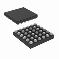
IC AMP AUDIO MONO AB MIC 36USMD
Manufacturer
National Semiconductor
Series
PowerWise®r
Type
Class ABr
Datasheet
1.LMV1088RLNOPB.pdf
(26 pages)
Specifications of LMV1088RL/NOPB
Output Type
1-Channel (Mono)
Voltage - Supply
2.7 V ~ 5.5 V
Features
Differential Inputs, I²C, Microphone, Mute
Mounting Type
Surface Mount
Package / Case
36-MicroSMDxt
Amplifier Class
AB
No. Of Channels
2
Supply Voltage Range
2.7V To 5.5V
Load Impedance
10kohm
Operating Temperature Range
-40°C To +85°C
Amplifier Case Style
SMD
No. Of Pins
36
Rohs Compliant
Yes
Lead Free Status / RoHS Status
Lead free / RoHS Compliant
Max Output Power X Channels @ Load
-
Other names
LMV1088RLTR


Symbol
THD+N Total Harmonic Distortion + Noise
CMRR Common Mode Rejection Ratio
PSRR Power Supply Rejection Ratio
Z
SNR
V
Z
T
ε
A
A
I
A
A
V
Absolute Maximum Ratings
If Military/Aerospace specified devices are required,
please contact the National Semiconductor Sales Office/
Distributors for availability and specifications.
Electrical Characteristics 3.3V and 5.0V
Unless otherwise specified, all limits guaranteed for T
11), preamplifier gain = 20dB, postamplifier gain = -2.5dB, R
V
Z
LOAD
A
I
DDQ
Supply Voltage
Storage Temperature
ESD Rating (Note 7)
ESD Rating (Note 8)
Junction Temperature (T
Mounting Temperature
A
VBM
OUT
OUT
CAL
BM
MR
MD
BM
PR
CR
IN
IN
M
P
Infrared or Convection (20 sec.)
Signal-to-Noise Ratio
Max Input Signal
AC Output Voltage
DC Output Voltage
Input Impedance
Output Impedance
Microphone Pre Amplifier Gain Range
Microphone Pre Amplifier Gain Adjustment
Resolution
Post Amplifier Gain Range
Post Amplifier Gain Adjustment Resolution f = 1kHz
Gain Compensation Range
Gain Matching Difference After Calibration
Calibration Duration
Microphone Bias Supply Voltage
Microphone Bias Supply Noise
Total available Microphone Bias Current
Supply Quiescent Current
Parameter
JMAX
)
6.0V
-85°C to +150°C
2000V
200V
150°C
235°C
(Note 4)
f = 1kHz, V
f = 1kHz and THD+N < 1%
f = 1kHz, preamp gain = 36dB
V
f = 1kHz, V
R
C
f = 1kHz
f = 1kHz
f = 1kHz Pass Through Mode and
Summing Mode
f = 1kHz Noise Canceling Mode
(Note 12)
f = 300Hz – f = 3400Hz
f = 300Hz
f = 1kHz
f = 3kHz
Input Referred, Input AC grounded
f = 217Hz (100mV
f = 1kHz (100mV
f = 1kHz,
I
A-Weighted
V
BIAS
IN
IN
J
LOAD
LOAD
= 25°C, V
= 30mV
= 0V
= 1mA
L
= 100kΩ, and C
IN
IN
P-P
5
DD
= 18mV
= 18mV
Conditions
(Note 4)
= 3.3V and 5.0V, V
Operating Ratings
Thermal Resistance
θ
Soldering Information See AN-112 “microSMD Wafers Level
Chip Scale Package.”
Supply Voltage
I
Temperature Range
P-P
2
CV
P-P
)
JA
PP
)
P-P
DD
(microSMD)
, A-Weighted
(Note 13)
L
= 4.7pF.
IN
= 18mV
-2.5 – 9.5
(Note 9)
Typical
P-P
6 – 36
0 – 12
500
800
100
150
0.1
2.0
60
97
85
80
60
10
, pass through mode (Note
2
3
1
(Note 5)
LMV1088
(Note 10)
Limits
770
2.7V to 5.5V
1.8V to 5.5V
−40°C to 85°C
0.5
0.5
0.5
1.2
1.5
10
10
±3
70°C/W
www.national.com
Units (Limits)
mA (max)
ms (max)
pF (max)
dB (max)
dB (max)
dB (max)
dB (max)
mA (min)
kΩ (min)
mV
μV
mV
mV
dB
kΩ
dB
dB
dB
dB
dB
dB
dB
dB
%
Ω
V
RMS
RMS
P-P
Related parts for LMV1088RL/NOPB
Image
Part Number
Description
Manufacturer
Datasheet
Request
R

Part Number:
Description:
Manufacturer:
National Semiconductor
Datasheet:
Part Number:
Description:
National Semiconductor [8-Bit D/A Converter]
Manufacturer:
National Semiconductor
Datasheet:
Part Number:
Description:
National Semiconductor [Media Coprocessor]
Manufacturer:
National Semiconductor
Datasheet:
Part Number:
Description:
Digitally Controlled Tone and Volume Circuit with Stereo Audio Power Amplifier, Microphone Preamp Stage and National 3D Sound
Manufacturer:
National Semiconductor
Datasheet:
Part Number:
Description:
Digitally Controlled Tone and Volume Circuit with Stereo Audio Power Amplifier, Microphone Preamp Stage and National 3D Sound
Manufacturer:
National Semiconductor
Datasheet:
Part Number:
Description:
AC97 Rev 2 Codec with Sample Rate Conversion and National 3D Sound
Manufacturer:
National Semiconductor
Part Number:
Description:
Manufacturer:
National Semiconductor
Datasheet:
Part Number:
Description:
Manufacturer:
National Semiconductor
Datasheet:
Part Number:
Description:
General Purpose, Low Voltage, Low Power, Rail-to-Rail Output Operational Amplifiers
Manufacturer:
National Semiconductor
Datasheet:
Part Number:
Description:
8-bit 20 MSPS flash A/D converter.
Manufacturer:
National Semiconductor
Datasheet:
Part Number:
Description:
Low Noise Quad Operational Amplifier
Manufacturer:
National Semiconductor
Datasheet:
Part Number:
Description:
Quad Differential Line Receivers
Manufacturer:
National Semiconductor
Datasheet:
Part Number:
Description:
Quad High Speed Trapezoidal? Bus Transceiver
Manufacturer:
National Semiconductor
Datasheet:
Part Number:
Description:
Dual Line Receiver
Manufacturer:
National Semiconductor
Datasheet: