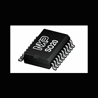
P87LPC769 NXP Semiconductors, P87LPC769 Datasheet - Page 34

P87LPC769
Manufacturer Part Number
P87LPC769
Description
The P87LPC769 is a 20-pin single-chip microcontroller designed forlow pin count applications demanding high-integration, low costsolutions over a wide range of performance requirements
Manufacturer
NXP Semiconductors
Datasheet
1.P87LPC769.pdf
(62 pages)
Available stocks
Company
Part Number
Manufacturer
Quantity
Price
Company:
Part Number:
P87LPC769BD
Manufacturer:
PHILIPS
Quantity:
64
Company:
Part Number:
P87LPC769FD
Manufacturer:
PHILIPS
Quantity:
53
Philips Semiconductors
Table 9. Sources of Wakeup from Power Down Mode
Some chip functions continue to operate and draw power during
Power Down mode, increasing the total power used during Power
2002 Mar 12
Wakeup Source
External Interrupt 0 or 1
Keyboard Interrupt
Comparator 1 or 2
Watchdog Timer Reset
Watchdog Timer Interrupt
Brownout Detect Reset
Brownout Detect Interrupt
Reset Input
A/D converter
Low power, low price, low pin count (20 pin)
microcontroller with 4 kB OTP 8-bit A/D, and DAC
Conditions
The corresponding interrupt must be enabled.
The keyboard interrupt feature must be enabled and properly set up. The corresponding interrupt must be
enabled.
The comparator(s) must be enabled and properly set up. The corresponding interrupt must be enabled.
The watchdog timer must be enabled via the WDTE bit in the UCFG1 EPROM configuration byte.
The WDTE bit in the UCFG1 EPROM configuration byte must not be set. The corresponding interrupt must
be enabled.
The BOD bit in AUXR1 must not be set (brownout detect not disabled). The BOI bit in AUXR1 must not be
set (brownout interrupt disabled).
The BOD bit in AUXR1 must not be set (brownout detect not disabled). The BOI bit in AUXR1 must be set
(brownout interrupt enabled). The corresponding interrupt must be enabled.
The external reset input must be enabled.
Must use internal RC clock (RCCLK = 1) for A/D converter to work in Power Down mode. The A/D must be
enabled and properly set up. The corresponding interrupt must be enabled.
31
Down. These include the Brownout Detect, Watchdog Timer,
Comparators, and the A/D Converter.
P87LPC769
Preliminary data


