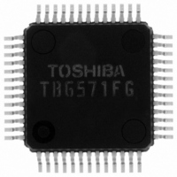
TB6571FG(O,EL) Toshiba, TB6571FG(O,EL) Datasheet - Page 20

TB6571FG(O,EL)
Manufacturer Part Number
TB6571FG(O,EL)
Description
IC DC MOTOR CTRLR BRUSHLSS 52QFP
Manufacturer
Toshiba
Specifications of TB6571FG(O,EL)
Applications
DC Motor Controller, Brushless (BLDC), 3 Phase
Number Of Outputs
1
Voltage - Supply
10 V ~ 28 V
Operating Temperature
-30°C ~ 85°C
Mounting Type
Surface Mount
Package / Case
52-QFP
Mounting Style
SMD/SMT
Lead Free Status / RoHS Status
Lead free / RoHS Compliant
Current - Output
-
Voltage - Load
-
Lead Free Status / Rohs Status
Lead free / RoHS Compliant
Other names
TB6571FGTR
Available stocks
Company
Part Number
Manufacturer
Quantity
Price
Electrical characteristics
Supply current
Hall
amplifier
Ready
circuit
FG
amplifier
FG
hysteresis
comparat-
or
Control
input
circuit
Fref input
circuit
Charge pump voltage
Energization signal output voltage
Internal supply voltage output
Current limiter circuit reference
voltage
Internal clock frequency
Dead time
Phase lead angle
controller
Characteristics
Common-mode input
voltage range
Input amplitude range
Input hysteresis
Input current
Remaining output voltage
Output leakage current
Input offset voltage
Remaining output voltage
(upper)
Remaining output voltage
(lower)
Reference voltage
Hysteresis width
Remaining output voltage
Output leakage current
Input voltage (H)
Input voltage (L)
Input current (H)
Input current (L)
Input voltage (H)
Input voltage (L)
Input current (H)
Input current (L)
Upper clamp limit
(V
CC
VO (U)-(H)
VO (U)-(L)
VO (L)-(H)
VOFG (H)
VO (L)-(L)
IinCW (H)
VinSB (H)
VOFG (L)
IinCW (L)
VinSB (L)
VCMRH
VOSFG
Symbol
VrefFG
TOFF1
TOFF2
VhysH
VhysS
Vin(H)
VCER
VCES
Vin(L)
Iin (H)
ACLH
Iin (L)
Vref1
Vref2
= 24 V, Ta = 25°C)
I
I
VLS
V
IinH
Vdc
ILR
CC1
CC2
VH
VG
fx2
DD
Circuit
Test
20
Start
Stop
(Design target value)
VCMRH = 2.5 V, 1-phase
Open collector output,
ICER = 2 mA
Vready = 6 V
IFG = 100 µA (source current)
IFG = 100 µA (sink current)
Open collector output,
ICES = 1 mA
VFGS = 6 V
CW/CCW, STB, BRAKE,
START
CW/CCW, STB, BRAKE,
START
Vin = 5 V
Vin = GND
Fref
Fref
Vin = 5 V
Vin = GND
LA (U)/LB (U)/LC (U),
Io = 20 mA
LA (L) /LB (L) /LC (L),
Io = 20 mA
R=10kΩ,C=51pF
R=10kΩ,C=51pF
R=10kΩ,C=51pF
Test conditions
V
Vref1
−1.2
0.15
−1.0
7.25
0.23
Min
6.0
1.5
± 4
2.2
2.0
2.0
CC
VG
4.5
4.5
8.2
3.4
1.2
1.2
5.4
50
70
70
0
0
7
+
Vref1/
V
Typ.
12.0
7.75
0.25
100
100
9.0
0.2
CC
5.0
5.0
8.7
3.8
1.7
1.7
± 8
29
2
8
+
TB6571FG
2005-04-15
V
Vref1
Max
18.0
12.6
± 12
0.25
8.25
0.27
130
130
VG
3.5
0.5
± 7
1.2
2.8
0.5
5.5
0.8
5.5
0.8
CC
0.5
0.5
5.5
5.5
9.2
4.2
2.2
2.2
1
1
1
1
1
9
+
mVpp
Units
MHz
mΑ
mV
mV
µA
µA
µA
µA
µA
µs
V
V
V
V
V
V
V
V
V
V
V
V
°


