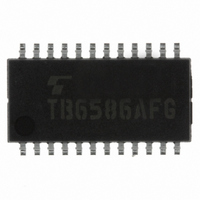
TB6586AFG(O,EL,DRY) Toshiba, TB6586AFG(O,EL,DRY) Datasheet - Page 9

TB6586AFG(O,EL,DRY)
Manufacturer Part Number
TB6586AFG(O,EL,DRY)
Description
IC BRUSHLESS MOTOR CTLR 24SSOP
Manufacturer
Toshiba
Datasheet
1.TB6586FGOELDRY.pdf
(20 pages)
Specifications of TB6586AFG(O,EL,DRY)
Applications
DC Motor Controller, Brushless (BLDC), 3 Phase
Number Of Outputs
1
Voltage - Load
4.5 V ~ 16.5 V
Voltage - Supply
6.5 V ~ 16.5 V
Operating Temperature
-30°C ~ 85°C
Mounting Type
Surface Mount
Package / Case
24-SSOP
Lead Free Status / RoHS Status
Lead free / RoHS Compliant
Current - Output
-
Other names
TB6586AFGTR
Functional Description
1. Basic operation
2. V
3. Function to stabilize the bootstrap voltage
Output Waveform
Lower (UL, VL, WL)
Upper (UH, VH, WH)
At startup, the motor runs at 120° energization. When the position detection signal reaches a revolution
count of fs = 5 Hz or higher, the rotor position is extrapolated from the position detection signal and output
is activated using the lead angle based on the LA signal.
(1)
(2)
(3)
The product is equipped with a bootstrap capacitor charging function that supports the output level of the
bootstrap method.
(1)
SP
Startup - 5 Hz: 120° energization
5 Hz or higher: 120° energization or 150° energization *
voltage command signal function
*: At 5 Hz or higher, operation is performed in accordance with commands from RESET and LA pins.
When voltage instruction is input at V
Output is turned off (gate block protection).
When voltage instruction is input at 1.0 V < V
The lower transistor is turned on at a regular (carrier) cycle. (ON duty: T
When a voltage instruction is input at V
The drive signal is output using the energization method configured using the RESET pin.
Note: At startup, to charge the upper transistor gate power supply, turn the lower transistor on for a fixed
*: The maximum ON duty is T
If the V
WH) based on the carrier cycle. If the output waveform is upper phase (UH, VH, WH), the OFF signal
(Low) is output.
When the motor is running at 5 Hz or lower and in reverse (in accordance with the timing chart), it will
be driven at 120° energization for a lead angle of 0°.
Example:
T
Example: f
on
time with 1.0 V < V
PWM ON Duty (Upper)
= 18/f
SP
*95%
input current is 1.0 V < V
(typ.)
osc
osc
0
UH
UL
If f
If f
= 5 MHz T
osc
osc
(1)
1.0 V
= 5 MHz, then ON time = 48 µs (typ.) (f
= 4 MHz, then ON time = 60 µs (typ.) (f
SP
on
< = 2.1 V.
(2)
on
= 3.6 µs
2.1 V
= 95% (typ.) when V
SP
(3)
SP
< = 2.1 V, the ON signal is output to the lower phase (UL, VL,
5.4 V
SP
< = 1.0 V:
> 2.1 V:
9
SP
Magnified view
< = 2.1 V (refresh operation):
V
sp
SP
fs = f
T
= 5.4 V (typ.).
on
Approximately 5 Hz if f
osc
c
c
= 19.8 kHz)
= 15.9 kHz)
/ (120 × 2
5
× 2
on
8
= 18/f
)
TB6586FG/AFG
osc
osc
)
= 5 MHz.
2007-08-03


