ATICE50POD Atmel, ATICE50POD Datasheet
ATICE50POD
Specifications of ATICE50POD


Related parts for ATICE50POD


ATICE50POD Summary of contents
Page 1
ICE50 .............................................................................................. User Guide ...
Page 2
...
Page 3
ICE50 User Guide Table of Contents Section 1 Preface ................................................................................................. 1-1 1.1 About this Manual .....................................................................................1-1 1.1.1 Warnings ............................................................................................1-1 1.1.2 Tips.....................................................................................................1-1 1.1.3 Workaround ........................................................................................1-1 1.1.4 Checklists ...........................................................................................1-1 1.1.5 Related Documentation ......................................................................1-2 1.2 ICE50 Firmware History ............................................................................1-2 1.2.1 Version 1.0 .........................................................................................1-2 ...
Page 4
Table of Contents ii 2523A–AVR–11/02 3.3 POD Bay ...................................................................................................3-4 3.3.1 Removing POD from POD Bay ..........................................................3-4 3.3.2 Inserting POD Into POD Bay ..............................................................3-4 3.3.3 Expansion Bay....................................................................................3-5 3.3.4 USB Connector...................................................................................3-5 3.3.5 RS-232C Connector ...........................................................................3-5 3.3.6 Reset Button.......................................................................................3-5 3.3.7 Power Switch......................................................................................3-5 3.3.8 ...
Page 5
ICE50 User Guide Section 4 Connecting ICE50................................................................................. 4-1 4.1 Connecting ICE50 for Emulation...............................................................4-1 4.2 Connecting ICE50 to host PC ...................................................................4-1 4.3 Connecting the Probe to the Target Board ...............................................4-1 4.3.1 Connecting PDIP Adapters.................................................................4-1 4.3.2 Connecting TQFP Adapters ...............................................................4-3 4.4 ICE50 ...
Page 6
Table of Contents iv 2523A–AVR–11/02 Section 8 Troubleshooting .................................................................................... 8-1 8.1 Troubleshooting Guide..............................................................................8-1 ICE50 User Guide ...
Page 7
About this Manual 1.1.1 Warnings 1.1.2 Tips 1.1.3 Workaround 1.1.4 Checklists ICE50 User Guide This manual is using the nomenclature described in this section to show warnings, tips, workarounds etc. This manual contains important warnings to prevent damage to ...
Page 8
... User Break 1-2 2523A–AVR–11/02 The following electronic documents from Atmel microcontrollers, and of the debugging tools. All documents can be found on the Atmel Products CD-ROM enclosed in the ICE50 kit. For more information and document updates, please visit our web site: www.atmel.com. ® ...
Page 9
... Reporting Problems ICE50 User Guide Problems with AVR Studio can be reported to avr@atmel.com. Problems with beta releases can be reported to avrbeta@atmel.com. Preface 1-3 2523A–AVR–11/02 ...
Page 10
Preface 1-4 2523A–AVR–11/02 ICE50 User Guide ...
Page 11
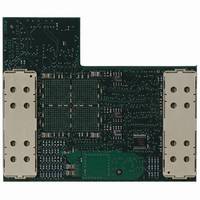
... ICE50 Contents ICE50 User Guide ATICE50 is an advanced In-Circuit Emulator that covers a wide range of the eight bits AVR microcontrollers from Atmel. This section gives a brief introduction to it’s features. Figure 2-1. The ATICE50 contains the following items: ICE50 Main Unit/Pod/Two FPC (Flexible Printed Circuit) Cables & Probe Personality Adapters for: – ...
Page 12
... Application Notes – AVR Studio 4.00 or Later ICE50 Quick Start Guide The ICE50 In-circuit Emulator is a High-end Emulator from Atmel designed to emulate a wide range of AVR devices. The ICE50 is controlled by AVR Studio 4.0 or later. Present, the following devices are supported: – ATtiny26 – ...
Page 13
System Requirements 2.3.1 Hardware Requirements 2.3.2 Software Requirements 2.3.3 Target Hardware Requirements 2.3.4 Operating Conditions 2.3.5 Host Interface ICE50 User Guide The following minimum requirements apply for the ICE50. For using the ICE50 with AVR Studio, a Pentium 233 ...
Page 14
Introduction 2-4 2523A–AVR–11/02 ICE50 User Guide ...
Page 15
General Hardware Description 3.1.1 What is an In-Circuit Emulator? ICE50 User Guide This setion describes the different components of the ATICE50 in detail. In this section a brief description of emulation is given, and a closer look at the ...
Page 16
General Description 3.2 Main Emulator Unit 3.2.1 Emulator Unit 3.2.2 Status LEDs 3-2 2523A–AVR–11/02 The main emulator unit contains the “brain” of the ICE50. The main emulator unit is shown in Figure 3-1. The main unit contains the control logic, ...
Page 17
Red Power LED 3.2.2.2 Multi Color Mode LED 3.2.2.3 Green Status LED ICE50 User Guide The red LED is the power indicator LED. This will be lit if power on the ICE50 is turned on and the power system ...
Page 18
... Both the I/O pins and the analog features are implemented on the POD board. If new AVR devices are made available to the market that contain I/O or analog features that cannot be emulated by the current POD, Atmel is dedicated to create new POD modules that support the functionality of the new devices. ...
Page 19
Expansion Bay 3.3.4 USB Connector 3.3.5 RS-232C Connector 3.3.6 Reset Button 3.3.7 Power Switch ICE50 User Guide Figure 3-5. Inserting POD Into POD Bay The expansion connector is intended for future use, and not used in the current version ...
Page 20
General Description 3.3.8 Power Connector 3.4 Personality Adapter Description 3.4.1 Personality Adapter Description 3-6 2523A–AVR–11/02 Figure 3-7. Power Switch and Connector The Power Connector on the ICE50 system is a standard type with 2.1 mm center tap. Ground should be ...
Page 21
Connecting the Personality Adapter to the Probe 3.4.2 t26 Personality Adapter 3.4.2.1 Supported Devices ICE50 User Guide When connecting the Personality Adapter and the Probe, make sure that the Probe is connected with the correct orientation. The connectors will ...
Page 22
General Description 3.4.3 t28 and t29 Personality Adapter 3.4.3.1 Supported Devices 3.4.4 m8 Personality Adapter 3.4.4.1 Supported Devices 3-8 2523A–AVR–11/02 The t28 Personality adapter is a PDIP adapter for t28 devices. The footprint is a stan- dard 28-lead 0.300" wide, ...
Page 23
Personality Adapter 3.4.5.1 Supported Devices 3.4.6 m162 Personality Adapter 3.4.6.1 Supported Devices ICE50 User Guide The m32 Personality adapter is a PDIP adapter for m32/m16 devices. The footprint is a standard 40-lead 0.600" wide, PDIP package. If the ...
Page 24
General Description 3.4.7 m128 Personality Adapter 3.4.7.1 Supported Devices 3.4.8 m169 Personality Adapter 3.4.8.1 Supported Devices 3-10 2523A–AVR–11/02 The m128 Personality Adapter is a TQFP64 adapter, and it consists of two modules. The bottom module has the TQFP footprint, and ...
Page 25
... The ICE50 POD implements all digital I/O and analog functionality of the current AVR family of devices. If new AVR devices are made available to the market that contain I/O or analog features that cannot be emulated by the current POD, Atmel is dedicated to create new POD modules that support the functionality of the new devices. ...
Page 26
General Description 3.5.2 Digital I/O 3-12 2523A–AVR–11/02 The Digital IO ports of the ICE50 are realized as shown in Figure 3-17 using CMOS buff- ers and voltage converters. Figure 3-17. Digital I/O DIGITAL I/O LEVEL CONVERTER V Emulator CC PULLUP ...
Page 27
ICE50 User Guide Table 3-3. Data Direction Delay Typical Value (2V Target) ( OHL ( OLH ( IHL ( ILH Notes: 1. tOHL = Time from clearing the ...
Page 28
General Description 3.5.3 Analog Comparator 3.5.4 A/D Converter 3-14 2523A–AVR–11/02 The Analog Comparator is built around a high speed comparator and a CMOS output buffer/voltage converter. Figure 3-20 shows the Analog Comparator block diagram. The total propagation delay from the ...
Page 29
Power System Description 3.6.1 Power Supply 3.6.2 ICE50 Power System The ICE50 has an internal power regulator designed to deliver regulated voltages for ICE50 User Guide The ADC is built using analog multiplexers, programmable gain instrumentation amplifi- ers and ...
Page 30
General Description 3.6.3 Target Application Power Requirements 3-16 2523A–AVR–11/02 The Probe and parts of the POD are powered by the target application power system. The dynamic power requirements of the Probe/POD will not differ significantly from the power requirements of ...
Page 31
Probe Description 3.7.1 Probe Description ICE50 User Guide The ICE50 probe is the link between the flex cable going out from the POD and the Per- sonaliy Adapter that fits into the target application. The main purpose of the ...
Page 32
General Description 3.7.1.1 Available Clock Options 3.7.1.2 ICE50 Probe version A9902.3.1200.E 3.7.2 External Clock Signal 3.7.3 Internal Clock Signal Provided by AVR Studio 3-18 2523A–AVR–11/02 Figure 3-25. External Clock Enable Enable The current version of the Probe has some restrictions ...
Page 33
External 32 kHz RTC Crystal 3.7.5 Internal RC Oscillator 3.7.6 External Crystal and External Resonator 3.7.7 External RC Oscillator 3.8 Test Adapter ICE50 User Guide The Asynchronous Timers in the emulated part may be clocked by an external 32 ...
Page 34
... Finally, the test program will show the status of the test. Note: AVR Studio 4.0 or later is required for ICE50 support. AVR Studio 3.x versions will not work with ICE50! Tip! AVR Studio is constantly being updated. Check for upgrades at www.atmel.com. ICE50 User Guide ...
Page 35
Connecting ICE50 for Emulation 4.2 Connecting ICE50 to host PC 4.3 Connecting the Probe to the Target Board 4.3.1 Connecting PDIP Adapters ICE50 User Guide ICE50 connects to both the PC where the firmware development is being made and ...
Page 36
Connecting ICE50 4-2 2523A–AVR–11/02 connecting or disconnecting the ICE50 from the host PC, make sure that the ICE50 is not powered. 1. Inserting the personality adapter. Make sure that pin 1 on the personality adapter corresponds with pin 1 on ...
Page 37
Connecting TQFP Adapters ICE50 User Guide The m128 TQFP adapter consists of two parts: The bottom part that should be soldered into the target application, and the top part that interface with the ICE50 Probe. When mounting the TQFP ...
Page 38
Connecting ICE50 4.4 ICE50 Power-up Sequence 4-4 2523A–AVR–11/02 Warning! Every design precaution is taken so that the probe and ICE50 POD should not be damaged if incorrectly placed. However, selecting wrong adapter, or placing the adapter with wrong orientation may ...
Page 39
ICE50 Emulator Options ICE50 User Guide Configuring AVR Studio When the ICE50 is properly connected to the target application, the next step is to set up the correct device configuration in AVR Studio. This is required when an application ...
Page 40
Configuring AVR Studio 5.2 AVR Studio Configuration Quick Start Guide 5-2 2523A–AVR–11/02 Follow the procedure described below to configure the ICE50: 1. Connect the ICE50 and start AVR Studio. See Connecting ICE50 for a more detailed description. 2. Select between ...
Page 41
Device Selection ICE50 User Guide 5. Press the next button. Now select ICE50 as target and then chose the part to emulate. Press finish to complete the wizard. AVR Studio will now be ready for use. See Figure 5-3. ...
Page 42
Configuring AVR Studio 5-4 2523A–AVR–11/02 Figure 5-4. Device Selection In addition two buttons called ICE Reset and Set Default are located in the lower left cor- ner. See Figure 5-4. The ICE Reset button resets the ICE while the set ...
Page 43
Fuses and Lock Bits ICE50 User Guide The Fuse- and Lock bit settings in the part can be viewed and configured from AVR Stu- dio. The Fuse settings can only be viewed and not edited in the “Fuse and ...
Page 44
Configuring AVR Studio 5-6 2523A–AVR–11/02 Figure 5-6. Extended Fuse Settings 2. By pressing “Low Fuse” the tree expands and it is possible to see the settings for this Fuse. “0” indicates on, “1” indicates off. The Fuse settings can not ...
Page 45
ICE50 User Guide Figure 5-8. High Fuse Settings Tip! Not all fuse settings are supported by the ICE50. The following fuses are ignored: – OCDEN. On Chip debug is not available in ICE50. – SPIEN. Serial Programming not available. – ...
Page 46
Configuring AVR Studio 5.5 Lock Bits 5-8 2523A–AVR–11/02 By pressing Lock bits the tree expands and it is possible to see the Lock bit settings. “0” indicates on, “1” indicates off. The fuse settings can not be edited here. See ...
Page 47
ICE Status ICE50 User Guide In AVR Studio go to Debug->ICE50 Options. Highlight ICE Status. The report which appear describes the different modules with respect to software version and firmware version. See Figure 5-10. In addition two buttons called ...
Page 48
Configuring AVR Studio 5-10 2523A–AVR–11/02 Figure 5-11. ICE Staus Window ICE50 User Guide ...
Page 49
Boot Block Options ICE50 User Guide In AVR Studio go to Debug->ICE50 options. Highlight Boot Block Options. Four different pulldown menus will appear. See Figure 5-12. The four menus are: 1. Boot Size. Select between the available Boot Sizes ...
Page 50
... ICE reset performs the same reset as the reset button on the back of the ICE50. AVR Studio will check if newer files are available in the ICE50 dat file, and prompt the user whether an upgrade should be performed. AVR Studio is continously updated. Check the Atmel web site, www.atmel.com, for upgrades. ICE50 User Guide ...
Page 51
Upgrading the ICE50 Firmware ICE50 User Guide The ICE50 firmware can be upgraded from AVR Studio. In AVR Studio go to Tools ->ICE50 Upgrade. The window as shown in Figure 5-14 will appear. Figure 5-14. ICE50 Upgrade Window From ...
Page 52
Configuring AVR Studio 5-14 2523A–AVR–11/02 Figure 5-15. Version Information ICE50 User Guide ...
Page 53
Electrical Compatibility 6.1.1 Power 6.1.2 I/O Lines ICE50 User Guide Special Considerations The ICE50 accurately emulates most AVR features. However, there are some differ- ences worth noting. Clock Options A/D Converter Accuracy Differences from actual part Electrical Compatibility Sleep ...
Page 54
Special Considerations 6.2 Sleep Mode 6.3 Target Hardware Requirements 6.4 Clock Options 6.5 Differences Between Emulator and Part 6-2 2523A–AVR–11/02 Figure 6-2. I/O Lines Resetable Probe I/O Fuse When in sleep mode there will be no power reduction as can ...
Page 55
Enabling Trace in AVR Studio ICE50 User Guide The ICE50 contains a 144-bit wide, 128K levels deep Trace Buffer. This document describes the contents of the AVR Studio Trace Buffer view enable Trace in AVR Studio select ...
Page 56
Trace 7.2 The Trace Window 7-2 2523A–AVR–11/02 Figure 7-3. Multiple Start and Stop Trace The Function ID numbers can be selected from the trace toolbar. In Figure 7-4 Function ID “2” is selected from a drop down menu. Figure 7-4. ...
Page 57
ICE50 User Guide of the Program Counter, i.e the address in the Program Memory of the instruction currently being executed. For multicycle instructions, the contents of this column may contain other values. See the description of the various ...
Page 58
Trace 7.3 Contents of Trace Window Based on Instruction (ICE50) Table 7-1. Arithmetic and Logic Instructions Instruction PMem Addr INSTA[0..15] [PC[A0..22] ADD Rd,Rr Address of instruction ADC Rd, Rr Address of instruction 1. Address of instruction ADIW Rdl,K 2. Address ...
Page 59
Table 7-1. Arithmetic and Logic Instructions (Continued) Instruction PMem Addr INSTA[0..15] [PC[A0..22] 1. Address of instruction 2. MUL Rd, Rr Address of next instruction 1. Address of instruction MULS Rd Address of next instruction 1. Address of instruction ...
Page 60
Trace Table 7-2. Data Transfer Instructions Instruction INSTA[0..15] PMem Addr [PC[A0..22] (1) MOV Rd, Rr Address of instruction (1) MOVW Rd, Rr Address of instruction (1) LDI Rd, K Address of instruction 1. Address of instruction (1) LD Rd, X ...
Page 61
Table 7-2. Data Transfer Instructions (Continued) Instruction INSTA[0..15] PMem Addr [PC[A0..22] 1. Address of instruction (1) LDS Rd Address of address-part of instruction 1. Address of instruction ( Address of next instruction 1. Address ...
Page 62
Trace Table 7-2. Data Transfer Instructions (Continued) Instruction INSTA[0..15] PMem Addr [PC[A0..22] 1. Address of instruction LPM 2. Address of next instruction 3. Word address of data read 1. Address of instruction LPM Rd Address of next instruction ...
Page 63
Table 7-3. Branch Instructions Instruction INSTA PMem Addr [0..15] [PC[A0..22] 1. Address of instruction RJMP 2. N/A 1. Address of instruction IJMP 2. N/A 1. Address of instruction 2. Address of address-part JMP of instruction 3. N/A 1. Address of ...
Page 64
Trace Table 7-3. Branch Instructions (Continued) Instruction INSTA PMem Addr [0..15] [PC[A0..22] 1. Address of instruction 1. Address of instruction 2. Address of skipped (3) instruction SBRC 1. Address of instruction 2. Address of skipped instruction, first word 3. Address ...
Page 65
Table 7-3. Branch Instructions (Continued) Instruction INSTA PMem Addr [0..15] [PC[A0..22] 1. Address of instruction BRNE 1. Address of instruction (5) 2. N/A 1. Address of instruction BRCS 1. Address of instruction (5) 2. N/A 1. Address of instruction BRCC ...
Page 66
Trace Table 7-3. Branch Instructions (Continued) Instruction INSTA PMem Addr [0..15] [PC[A0..22] 1. Address of instruction BRVS 1. Address of instruction (5) 2. N/A 1. Address of instruction BRVC 1. Address of instruction (5) 2. N/A 1. Address of instruction ...
Page 67
Table 7-4. Bit and Bit-test Instructions Instruction INSTA [0..15] PMem Addr [PC [A0..22] LSL Address of instruction LSR Address of instruction ROL Address of instruction ROR Address of instruction ASR Address of instruction SWAP Address of instruction BSET Address of ...
Page 68
Trace Table 7-5. MCU Control Instructions Instruction INSTA PMem Addr [PC [0..15] [A0..22] NOP Address of instruction SLEEP Address of instruction WDR Address of instruction BREAK Address of instruction 7.4 Accessing External Data Memory (ICE50 Trace) 7.5 Interrupt Handling (ICE50 ...
Page 69
Reset (ICE50 Trace) 7.7 Save Trace Buffer to File (ICE50) 7.8 Sleep (ICE50 Trace) ICE50 User Guide Figure 7-8. Trace Window Output An External Reset, BOD (Brown-out Detection Watchdog Reset while Trace is enabled will be traced ...
Page 70
Trace 7-16 2523A–AVR–11/02 ICE50 User Guide ...
Page 71
Troubleshooting Guide ICE50 User Guide The troubleshooting guide gives advise if errors occurs. LEDs – Red Power LED does not turn on. See Power Supply Trouble – Multi color LED turns Red (error led lights up). See Configuration error ...
Page 72
Troubleshooting 8-2 2523A–AVR–11/02 ICE50 User Guide ...
Page 73
... No licenses to patents or other intellectual property of Atmel are granted by the Company in connection with the sale of Atmel products, expressly or by implication. Atmel’s products are not authorized for use as critical components in life support devices or systems. ...