OM11005 NXP Semiconductors, OM11005 Datasheet - Page 6
OM11005
Manufacturer Part Number
OM11005
Description
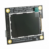
DISPLAY QVGA TFT FOR OM10100
Manufacturer
NXP Semiconductors
Datasheet
1.OM11005.pdf
(15 pages)
Specifications of OM11005
Accessory Type
LCD Display
For Use With/related Products
OM10100
Lead Free Status / RoHS Status
Not applicable / Not applicable
Other names
568-4358


Copyright 2007 © Embedded Artists AB
3.2 inch QVGA TFT Color LCD - User’s Guide
2 Design Description
This chapter describes the hardware design of the QVGA LCD Board.
2.1 Backlight Control
White LEDs are used as backlight on the display. The LED current is set to 15 mA. A step-
up DC/DC converted is used to generate a constant LED current. The switching frequency is
fixed to 1.2 MHz.
The intensity of the backlight (i.e., the white LEDs) is varied by varying the LED current.
There are two ways to very the LED current between 0-15 mA. A digital PWM signal is
needed with the same logic levels as the power supply (typically 3.3V).
The frequency of the modulation (PWM) signal should ideally be in the 5-10 kHz region.
2.2 On-board LCD Controller, display version 2
The display has an embedded controller, SSD1289 from Solomon Systech. This controller
chip has 1.3 Mbit embedded display RAM, which is enough for storing a complete
320xRGBx240 picture with 18 bit color depth.
There are a couple of interface alternatives to this controller. Either 18-bit, 16-bit, 9-bit or 8-
bit parallel interface or a serial interface. There are 4 pins that are used to configure the
interface. The table below lists the different options. L is statically tied to low logic level and
H is statically tied to high logic level.
18 bit
parallel
6800-
style i/f
H
H
H
L
•
•
Modulate the shutdown pin of the DC/DC converter (signal LED_SHDN). A low
input signal turn off the DC/DC converted and a high level activate it. A high duty
cycle on the PWM signal equals high intensity.
Modulate the current set pin of the DC/DC converter (signal LED_PWM). A low
input signal increase the LED current and a high level reduce it. A high duty cycle
on the PWM signal equals low intensity.
16 bit
parallel
6800-
style i/f
H
H
L
H
Does not matter. This pin is currently not used.
Does not matter. This pin is currently not used.
9 bit
parallel
6800-
style i/f
L
H
H
L
8 bit
parallel
6800-
style i/f
L
H
L
H
18 bit
parallel
8080-
style i/f
H
L
H
L
16 bit
parallel
8080-
style i/f
H
L
L
H
9 bit
parallel
8080-
style i/f
L
L
H
L
8 bit
parallel
8080-
style i/f
L
L
L
H
Configuration
pins
PS0 / CFG1
PS1 / CFG2
PS2 / CFG3
PS4 / CFG4
CFG5
CFG6
Page 6
Related parts for OM11005
Image
Part Number
Description
Manufacturer
Datasheet
Request
R

Part Number:
Description:
NXP Semiconductors designed the LPC2420/2460 microcontroller around a 16-bit/32-bitARM7TDMI-S CPU core with real-time debug interfaces that include both JTAG andembedded trace
Manufacturer:
NXP Semiconductors
Datasheet:

Part Number:
Description:
NXP Semiconductors designed the LPC2458 microcontroller around a 16-bit/32-bitARM7TDMI-S CPU core with real-time debug interfaces that include both JTAG andembedded trace
Manufacturer:
NXP Semiconductors
Datasheet:
Part Number:
Description:
NXP Semiconductors designed the LPC2468 microcontroller around a 16-bit/32-bitARM7TDMI-S CPU core with real-time debug interfaces that include both JTAG andembedded trace
Manufacturer:
NXP Semiconductors
Datasheet:
Part Number:
Description:
NXP Semiconductors designed the LPC2470 microcontroller, powered by theARM7TDMI-S core, to be a highly integrated microcontroller for a wide range ofapplications that require advanced communications and high quality graphic displays
Manufacturer:
NXP Semiconductors
Datasheet:
Part Number:
Description:
NXP Semiconductors designed the LPC2478 microcontroller, powered by theARM7TDMI-S core, to be a highly integrated microcontroller for a wide range ofapplications that require advanced communications and high quality graphic displays
Manufacturer:
NXP Semiconductors
Datasheet:
Part Number:
Description:
The Philips Semiconductors XA (eXtended Architecture) family of 16-bit single-chip microcontrollers is powerful enough to easily handle the requirements of high performance embedded applications, yet inexpensive enough to compete in the market for hi
Manufacturer:
NXP Semiconductors
Datasheet:
Part Number:
Description:
The XA-S3 device is a member of Philips Semiconductors? XA(eXtended Architecture) family of high performance 16-bitsingle-chip microcontrollers
Manufacturer:
NXP Semiconductors
Datasheet:

Part Number:
Description:
The NXP BlueStreak LH75401/LH75411 family consists of two low-cost 16/32-bit System-on-Chip (SoC) devices
Manufacturer:
NXP Semiconductors
Datasheet:
Part Number:
Description:
The NXP LPC3130/3131 combine an 180 MHz ARM926EJ-S CPU core, high-speed USB2
Manufacturer:
NXP Semiconductors
Datasheet:
Part Number:
Description:
The NXP LPC3141 combine a 270 MHz ARM926EJ-S CPU core, High-speed USB 2
Manufacturer:
NXP Semiconductors
Part Number:
Description:
The NXP LPC3143 combine a 270 MHz ARM926EJ-S CPU core, High-speed USB 2
Manufacturer:
NXP Semiconductors

Part Number:
Description:
The NXP LPC3152 combines an 180 MHz ARM926EJ-S CPU core, High-speed USB 2
Manufacturer:
NXP Semiconductors
Part Number:
Description:
The NXP LPC3154 combines an 180 MHz ARM926EJ-S CPU core, High-speed USB 2
Manufacturer:
NXP Semiconductors

Part Number:
Description:
Standard level N-channel enhancement mode Field-Effect Transistor (FET) in a plastic package using NXP High-Performance Automotive (HPA) TrenchMOS technology
Manufacturer:
NXP Semiconductors
Datasheet: