OM11005 NXP Semiconductors, OM11005 Datasheet - Page 7
OM11005
Manufacturer Part Number
OM11005
Description
DISPLAY QVGA TFT FOR OM10100
Manufacturer
NXP Semiconductors
Datasheet
1.OM11005.pdf
(15 pages)
Specifications of OM11005
Accessory Type
LCD Display
For Use With/related Products
OM10100
Lead Free Status / RoHS Status
Not applicable / Not applicable
Other names
568-4358


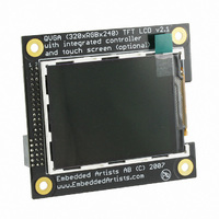
Copyright 2007 © Embedded Artists AB
3.2 inch QVGA TFT Color LCD - User’s Guide
3-wire
serial
SPI i/f
H
H
H
H
If the parallel interface is selected, there are two different interface types; either 6800 or
8080 style. See datasheet for details about timing and how the different control signals are
used.
Interface
8080 style
6800 style
If a serial interface is used, see the datasheet for details about timing and how the different
control signals are used. Note that maximum clock frequency is 13 MHz.
2.3 On-board touch screen Controller, display version 2
The touch screen controller used is TSC2046 from Texas Instruments. This chip has a SPI
interface and shares the SI, SO, SCK pins in the main interface connector, with the LCD
controller. Pin 45 must however be low (TSC2046 chip CS#) in order to communicate with
the touch screen controller. See TSC2046 datasheet for details about the serial interface.
2.4 On-board LCD Controller, display version 1
The display has an embedded controller, IS2102B from ISRON. This controller chip has 1.3
Mbit embedded display RAM, which is enough for storing a complete 320xRGBx240
picture with 18 bit color depth.
There are a couple of interface alternatives to this controller. Either 16-bit or 8-bit parallel
interface or a serial interface. There are 6 pins that are used to configure the interface. The
table below lists the different options. L is statically tied to low logic level and H is statically
tied to high logic level.
Does not matter. This pin is currently not used.
Does not matter. This pin is currently not used.
4-wire
serial
SP Ii/f
L
H
H
H
Description
i86 interface
RD/E signal is Read strobe
WR/RW signal is Write strobe
M68 interface
RD/E signal is Enable signal
WR/RW signal is RW signal (high = read, low = write)
6 bit
RGB i/f
H
H
L
L
16 bit
RGB +
4-wire
SPI i/f
L
H
L
L
18 bit
RGB +
4-wire
SPI i/f
H
L
L
L
Configuration
pins
PS0 / CFG1
PS1 / CFG2
PS2 / CFG3
PS4 / CFG4
CFG5
CFG6
Page 7
Related parts for OM11005
Image
Part Number
Description
Manufacturer
Datasheet
Request
R

Part Number:
Description:
NXP Semiconductors designed the LPC2420/2460 microcontroller around a 16-bit/32-bitARM7TDMI-S CPU core with real-time debug interfaces that include both JTAG andembedded trace
Manufacturer:
NXP Semiconductors
Datasheet:

Part Number:
Description:
NXP Semiconductors designed the LPC2458 microcontroller around a 16-bit/32-bitARM7TDMI-S CPU core with real-time debug interfaces that include both JTAG andembedded trace
Manufacturer:
NXP Semiconductors
Datasheet:
Part Number:
Description:
NXP Semiconductors designed the LPC2468 microcontroller around a 16-bit/32-bitARM7TDMI-S CPU core with real-time debug interfaces that include both JTAG andembedded trace
Manufacturer:
NXP Semiconductors
Datasheet:
Part Number:
Description:
NXP Semiconductors designed the LPC2470 microcontroller, powered by theARM7TDMI-S core, to be a highly integrated microcontroller for a wide range ofapplications that require advanced communications and high quality graphic displays
Manufacturer:
NXP Semiconductors
Datasheet:
Part Number:
Description:
NXP Semiconductors designed the LPC2478 microcontroller, powered by theARM7TDMI-S core, to be a highly integrated microcontroller for a wide range ofapplications that require advanced communications and high quality graphic displays
Manufacturer:
NXP Semiconductors
Datasheet:
Part Number:
Description:
The Philips Semiconductors XA (eXtended Architecture) family of 16-bit single-chip microcontrollers is powerful enough to easily handle the requirements of high performance embedded applications, yet inexpensive enough to compete in the market for hi
Manufacturer:
NXP Semiconductors
Datasheet:
Part Number:
Description:
The XA-S3 device is a member of Philips Semiconductors? XA(eXtended Architecture) family of high performance 16-bitsingle-chip microcontrollers
Manufacturer:
NXP Semiconductors
Datasheet:

Part Number:
Description:
The NXP BlueStreak LH75401/LH75411 family consists of two low-cost 16/32-bit System-on-Chip (SoC) devices
Manufacturer:
NXP Semiconductors
Datasheet:
Part Number:
Description:
The NXP LPC3130/3131 combine an 180 MHz ARM926EJ-S CPU core, high-speed USB2
Manufacturer:
NXP Semiconductors
Datasheet:
Part Number:
Description:
The NXP LPC3141 combine a 270 MHz ARM926EJ-S CPU core, High-speed USB 2
Manufacturer:
NXP Semiconductors
Part Number:
Description:
The NXP LPC3143 combine a 270 MHz ARM926EJ-S CPU core, High-speed USB 2
Manufacturer:
NXP Semiconductors

Part Number:
Description:
The NXP LPC3152 combines an 180 MHz ARM926EJ-S CPU core, High-speed USB 2
Manufacturer:
NXP Semiconductors
Part Number:
Description:
The NXP LPC3154 combines an 180 MHz ARM926EJ-S CPU core, High-speed USB 2
Manufacturer:
NXP Semiconductors

Part Number:
Description:
Standard level N-channel enhancement mode Field-Effect Transistor (FET) in a plastic package using NXP High-Performance Automotive (HPA) TrenchMOS technology
Manufacturer:
NXP Semiconductors
Datasheet: