MCP2150DM Microchip Technology, MCP2150DM Datasheet - Page 12
MCP2150DM
Manufacturer Part Number
MCP2150DM
Description
BOARD DEMO FOR MCP2150
Manufacturer
Microchip Technology
Specifications of MCP2150DM
Main Purpose
Interface, IrDA
Embedded
Yes, MCU, 8-Bit
Utilized Ic / Part
MCP2150
Primary Attributes
IrDA Controller with PIC18F MCU
Secondary Attributes
USB Interface
Processor To Be Evaluated
MCP2150, MCP2155
Processor Series
MCP215x
Interface Type
USB
Lead Free Status / RoHS Status
Lead free / RoHS Compliant
Lead Free Status / RoHS Status
Lead free / RoHS Compliant, Lead free / RoHS Compliant


MCP2150 Developer’s Board User’s Guide
1.3
DS51869A-page 12
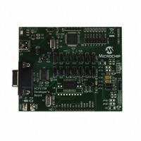
MCP2150 DEVELOPER’S BOARD FEATURES
The MCP2150 Developer’s Board has five functional blocks. These are:
• Power
• Host Microcontroller
• MCP2150
• Optical Transceiver circuitry
• RS-232 circuitry/interface
The MCP2150 Developer’s Board power can come from either the USB connection or
the power test points. The USB power is regulated to 3.3V, due to requirements from
the PIC18F65J50. To allow the other circuitry to operate at higher voltages, the
MCP2150 Developer’s Board has two power planes. One for the PIC18F65J50
circuitry and the other for the MCP2150/Optical Transceiver/RS-3238 Driver circuitry.
An LED is used to indicate when power is applied to the MCP2150/Optical
Transceiver/RS-232 Driver circuitry. A jumper (JP2) is used to tie the two power planes
together.
The MCP2150 uses a standard 11.0592 MHz crystal as the device clock. The Host
Controller can be programmed via the ICSP interface with user developed programs.
The MCP2150DM has the MCP2150 device mounted on the PCB (TSSOP package).
There is a DIP footprint (requires the TSSOP package to be removed) which allows the
MCP2150 to be easily updated if a device revision occurs.
The board supports up to four optical transceivers circuit implementations. Two
implementation share the same general circuit layout. Only one optical transceiver
circuit is installed at the time of manufacture. The others are for user implementation
and evaluation. Jumpers are used to select the optical transceiver that is used by the
system.
A MAX3238 compatible level-shifting IC has all the necessary hardware to support
connection of a RS-232 host through the DB-9 connector. The port can be connected
to a PC using a straight-through cable. Refer to the MCP2150 Data Sheet (DS21655)
for more information on the Host Interface signals.
The PIC18F65J50 has a maximum operational voltage of 3.6V. If the MCP2150
Developer’s Board is powered by the V
taken to ensure that the PIC18F65J50 is not over voltaged. The PIC18F65J50 can be
isolated from the MCP2150’s power plane by removing the jumper shunt on jumpers
JP1 and JP2.
Due to the flexibility of the interface between the MCP2150 and the PIC18F65J50, the
board has limited support for the MCP2155 device. This board’s firmware does not
support the MCP2155. To better understand the MCP2155’s Host Interface operation,
please refer to the MCP215X/40 Data Logger Demo Board (MCP215XDM) firmware.
CAUTION
NOTICE
DD
and GND Test Points, then care must be
© 2009 Microchip Technology Inc.
Related parts for MCP2150DM
Image
Part Number
Description
Manufacturer
Datasheet
Request
R

Part Number:
Description:
Manufacturer:
Microchip Technology Inc.
Datasheet:
Part Number:
Description:
Manufacturer:
Microchip Technology Inc.
Datasheet:
Part Number:
Description:
Manufacturer:
Microchip Technology Inc.
Datasheet:
Part Number:
Description:
Manufacturer:
Microchip Technology Inc.
Datasheet:
Part Number:
Description:
Manufacturer:
Microchip Technology Inc.
Datasheet:
Part Number:
Description:
Manufacturer:
Microchip Technology Inc.
Datasheet:
Part Number:
Description:
Manufacturer:
Microchip Technology Inc.
Datasheet:
Part Number:
Description:
Manufacturer:
Microchip Technology Inc.
Datasheet: