MCP2150DM Microchip Technology, MCP2150DM Datasheet - Page 20
MCP2150DM
Manufacturer Part Number
MCP2150DM
Description
BOARD DEMO FOR MCP2150
Manufacturer
Microchip Technology
Specifications of MCP2150DM
Main Purpose
Interface, IrDA
Embedded
Yes, MCU, 8-Bit
Utilized Ic / Part
MCP2150
Primary Attributes
IrDA Controller with PIC18F MCU
Secondary Attributes
USB Interface
Processor To Be Evaluated
MCP2150, MCP2155
Processor Series
MCP215x
Interface Type
USB
Lead Free Status / RoHS Status
Lead free / RoHS Compliant
Lead Free Status / RoHS Status
Lead free / RoHS Compliant, Lead free / RoHS Compliant


MCP2150 Developer’s Board User’s Guide
2.2
DS51869A-page 20
THE DEMO SYSTEM
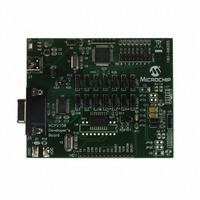
The demo system setup requires a Primary Device and a MCP2150 Developer’s Board
(Secondary Device). The Primary Device is a PC with an IR port (integrated IR port or
IR Dongle). The Secondary Device is the embedded system, which is the MCP2150
Developer’s Board.
The MCP2150 Developer’s Board can be powered by one of two sources:
• The USB sourced power
• The Power supply test points
For the demo descriptions, the board will be powered via USB, so, a PC with a UART
and USB port is required. The USB voltage is regulated to 3.3V, due to the PIC18
device’s voltage operating range.
This developer board either communicates between the DB-9 interface and the IR
interface or acts as an embedded system and communicates between the IR interface
and the PIC microcontroller.
2.2.1
The PIC18F65J50 firmware program looks at the state of the RD7:4 pins to determine
the board’s operation (program and Host UART baud rate).
The configuration of the JMP14:JMP1 jumpers determines how the UART signals are
connected between the MCP2150, PIC and the MAX3238 compatible driver.
The programs have the following operations:
• Data is directly passed from the IR interface to the MAX3238 device
• Data is passed from the IR interface to the MAX3238 device after passing through
• Once a data byte has been received by the PIC, the PIC continuously streams a
• The PIC echoes whatever character it receives, after changing the case (upper to
2.2.2
A PC with IR Port can be configured to operate as the Primary Device. The PC will need
to run an appropriate application program to communicate with the Secondary Device.
For a PC with IR port, this program will be HyperTerminal. The IRCOMM2K driver may
need to be installed so that HyperTerminal can communicate to the IR port as if it was
a serial port. When installing IRCOMM2K, select COM7 as the desired port.
Configuring the HyperTerminal program on the PC is shown in D.1.2 “Configuring
HyperTerminal to connect to the IrDA Port (Virtual Port)”.
The PC will run a second instance of HyperTerminal when running Demo #1 and Demo
#4. This instance of HyperTerminal will communicate to the PC’s serial port which will
be connected to the MCP2150DM’s serial port. This allows the transmitted data (from
the IR port) to be seen on the serial port (and vice versa). Configuring the
HyperTerminal program on the PC is shown in D.1.3 “HyperTerminal Configuration
for the Secondary Device”.
the PIC microcontroller
data table
lower, and lower to upper)
Note:
The PIC18F65J50 Firmware
The PC with IR Port
HyperTerminal should be disabled before establishing a connection
between the PC and the MCP2150 Developer’s Board. Make sure that any
other programs (e.g., HotSync
®
) connected to the IR ports are disabled.
© 2009 Microchip Technology Inc.
Related parts for MCP2150DM
Image
Part Number
Description
Manufacturer
Datasheet
Request
R

Part Number:
Description:
Manufacturer:
Microchip Technology Inc.
Datasheet:
Part Number:
Description:
Manufacturer:
Microchip Technology Inc.
Datasheet:
Part Number:
Description:
Manufacturer:
Microchip Technology Inc.
Datasheet:
Part Number:
Description:
Manufacturer:
Microchip Technology Inc.
Datasheet:
Part Number:
Description:
Manufacturer:
Microchip Technology Inc.
Datasheet:
Part Number:
Description:
Manufacturer:
Microchip Technology Inc.
Datasheet:
Part Number:
Description:
Manufacturer:
Microchip Technology Inc.
Datasheet:
Part Number:
Description:
Manufacturer:
Microchip Technology Inc.
Datasheet: