MCP2150DM Microchip Technology, MCP2150DM Datasheet - Page 15
MCP2150DM
Manufacturer Part Number
MCP2150DM
Description
BOARD DEMO FOR MCP2150
Manufacturer
Microchip Technology
Specifications of MCP2150DM
Main Purpose
Interface, IrDA
Embedded
Yes, MCU, 8-Bit
Utilized Ic / Part
MCP2150
Primary Attributes
IrDA Controller with PIC18F MCU
Secondary Attributes
USB Interface
Processor To Be Evaluated
MCP2150, MCP2155
Processor Series
MCP215x
Interface Type
USB
Lead Free Status / RoHS Status
Lead free / RoHS Compliant
Lead Free Status / RoHS Status
Lead free / RoHS Compliant, Lead free / RoHS Compliant


FIGURE 1-2:
© 2009 Microchip Technology Inc.
This jumper isolates the PIC19’s V
from the MCP2150 V
Section A.8 “Board - Power Layer”)
JP2
V
V
DD
DD
’s planes are connected
’s planes are isolated
1.3.1
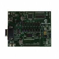
Figure 1-2 shows the jumpers used to control the power source, and the optical
transceiver used.
Jumper JP2 connects to the boards two power planes. The MCP2150 Developer’s
Board has a power plane for the PIC18F65J50 and the related circuitry, and a second
power plane for all other circuitry. Removing the jumper allows the MCP2150 portion to
operate through the full voltage range of the MCP2150 (2.0V to 5.5V). When JP2 is
connected, then the maximum voltage is restricted to the maximum voltage of the
PIC18F65J50 device (3.6V). See Figure A.8 for the power plane layout. When JP2 is
open, then the PIC18F65J50 must be isolated from the MCP2150. This is done with
the JMP1:JMP14 jumpers as well as the R26, R27, R28, and R29 resistors.
Jumpers JP1C1 and JP2C1 are used to connect the default installed optical transceiver
to the MCP2150’s RXPD and TXIR pins. There are footprints for two other optical
transceiver implementations. If either of those implementations are installed, then the
jumpers may be switched to the desired optical transceiver.
MCP2150 SELECTING SOURCES
DD
plane (see
Selecting Power Source, and Optical Transceiver Interface
Jumper Descriptions
DD
These two jumpers select the optical transceiver logic.
Both jumpers should connect the same pin positions.
JP1x1 and JP2x1
Optical Transceiver not connected
to MCP2150 IR Interface
Optical Transceiver connected to
MCP2150 IR Interface
Product Overview
DS51869A-page 15
Related parts for MCP2150DM
Image
Part Number
Description
Manufacturer
Datasheet
Request
R

Part Number:
Description:
Manufacturer:
Microchip Technology Inc.
Datasheet:
Part Number:
Description:
Manufacturer:
Microchip Technology Inc.
Datasheet:
Part Number:
Description:
Manufacturer:
Microchip Technology Inc.
Datasheet:
Part Number:
Description:
Manufacturer:
Microchip Technology Inc.
Datasheet:
Part Number:
Description:
Manufacturer:
Microchip Technology Inc.
Datasheet:
Part Number:
Description:
Manufacturer:
Microchip Technology Inc.
Datasheet:
Part Number:
Description:
Manufacturer:
Microchip Technology Inc.
Datasheet:
Part Number:
Description:
Manufacturer:
Microchip Technology Inc.
Datasheet: