MCP2150DM Microchip Technology, MCP2150DM Datasheet - Page 19
MCP2150DM
Manufacturer Part Number
MCP2150DM
Description
BOARD DEMO FOR MCP2150
Manufacturer
Microchip Technology
Specifications of MCP2150DM
Main Purpose
Interface, IrDA
Embedded
Yes, MCU, 8-Bit
Utilized Ic / Part
MCP2150
Primary Attributes
IrDA Controller with PIC18F MCU
Secondary Attributes
USB Interface
Processor To Be Evaluated
MCP2150, MCP2155
Processor Series
MCP215x
Interface Type
USB
Lead Free Status / RoHS Status
Lead free / RoHS Compliant
Lead Free Status / RoHS Status
Lead free / RoHS Compliant, Lead free / RoHS Compliant


2.1
TABLE 2-1:
© 2009 Microchip Technology Inc.
Note 1:
Qty
—
1
1
1
PC with: (1)
a) IR port
b) One USB port to power the
and
c) one serial port to
Serial Cable
USB Cable
MCP2150 Developer’s Board
INTRODUCTION
or
PC with USB/Serial port and
USB/Serial port to IR Dongle
(1)
MCP2150 Developer’s
Board
communicate to the
MCP2150 Developer’s
Board.
This can be done with one PC, but depending on the features of the selected PC, a second PC
may be required due to number of serial ports available (see Figure 2-1).
DEMO SYSTEM HARDWARE REQUIREMENTS
Hardware
Chapter 2. Installation and Operation
To demonstrate the operation of the MCP2150 Developer’s Board (Secondary Device)
a Primary Device is required. The Primary Device can be a PC with an IR port
(integrated IR port or IR Dongle).
The MCP2150 Developer’s Board default firmware program has four different
programs that are selected by the state of the RD7:6 pins.
These demonstration programs have the following operation:
• Demo #1 Operation - Direct IR / UART (DB-9) Mode
• Demo #2 Operation - Data Streaming Mode
• Demo #3 Operation - Echo Data Mode
• Demo #4 Operation - IR / UART (DB-9) Pass Through PIC Mode
Each demonstration program’s operation will be described in the Demo section.
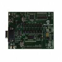
The component layout floor plan of the MCP2150 Developer’s Board (MCP2150DM)
PCB is shown in Figure 1-1 while Table 2-1 shows the hardware requirements to
demonstrate the MCP2150 Developer’s Board.
To keep the board cost low, only a portion of the MCP2150 Developer’s Board is tested.
This test covers the major portions of the system. The portions that are not tested are
shown in Appendix C. “Board Testing”.
MCP2150 DEVELOPER’S BOARD
Purpose
As a Primary Device, this device will initiate communication to
the MCP2150 Developer’s Board. The PC’s USB port will also
power the MCP2150 Developer’s Board.
Also:
The PC’s UART port will “talk” with the MCP2150’s UART
interface, while the PC’s IR port will “talk” with the MCP2150’s
IR interface.
The PC will run two instances of HyperTerminal, one
connected to the PC’s serial port (UART) and the other
connected to the PC’s IR port.
To connect the PC serial ports to the MCP2150 Developer’s
Board serial port.
To power the MCP2150 Developer’s Board from the PC’s USB
port.
This is the demonstration unit
USER’S GUIDE
DS51869A-page 19
Related parts for MCP2150DM
Image
Part Number
Description
Manufacturer
Datasheet
Request
R

Part Number:
Description:
Manufacturer:
Microchip Technology Inc.
Datasheet:
Part Number:
Description:
Manufacturer:
Microchip Technology Inc.
Datasheet:
Part Number:
Description:
Manufacturer:
Microchip Technology Inc.
Datasheet:
Part Number:
Description:
Manufacturer:
Microchip Technology Inc.
Datasheet:
Part Number:
Description:
Manufacturer:
Microchip Technology Inc.
Datasheet:
Part Number:
Description:
Manufacturer:
Microchip Technology Inc.
Datasheet:
Part Number:
Description:
Manufacturer:
Microchip Technology Inc.
Datasheet:
Part Number:
Description:
Manufacturer:
Microchip Technology Inc.
Datasheet: