EVALSF3-ICE3B2065P Infineon Technologies, EVALSF3-ICE3B2065P Datasheet
EVALSF3-ICE3B2065P
Specifications of EVALSF3-ICE3B2065P


Related parts for EVALSF3-ICE3B2065P


EVALSF3-ICE3B2065P Summary of contents
Page 1
...
Page 2
... Infineon Technologies Office. Infineon Technologies Components may only be used in life-support devices or systems with the express written approval of Infineon Technologies failure of such components can reasonably be expected to cause the failure of that life-support device or system affect the safety or effectiveness of that device or system ...
Page 3
... Page Subjects (major changes since last revision) Page 8-9 PCB drawing 40W 18V SMPS Evaluation Board with CoolSET™ F3 ICE3B2065P License to Infineon Technologies Asia Pacific Pte Ltd Jeoh Meng Kiat Luo Junyang Ho Kin Man Kok Siu Kam Eric We Listen to Your Comments Any information within this document that you feel is wrong, unclear or missing at all? Your feedback will help us to continuously improve the quality of this document ...
Page 4
ABSTRACT .......................................................................................................................................................................... 5 1 EVALUATION BOARD (18V, 2.22A).................................................................................................................... 5 2 LIST OF FEATURES ............................................................................................................................................... 6 3 TECHNICAL SPECIFICATION............................................................................................................................ 6 4 SCHEMATIC............................................................................................................................................................. 7 5 PCB.............................................................................................................................................................................. 8 5 OMPONENT IDE COMPONENT 5 ............................................................................................................................................. 9 OLDER IDE OPPER ...
Page 5
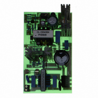
... Evaluation Board (18V, 2.22A) Figure 1 - EVALSF3-ICE3B2065P This document contains the list of features, the power supply specification, schematic, bill of material and the transformer construction documentation. Typical operating characteristics are presented at the rear of the report and consist of performance curves and scope waveforms. ...
Page 6
List of features • 650V avalanche rugged CoolMOS™ with built in switchable Startup Cell. • Active Burst Mode for lowest Standby Power @ light load controlled by Feedback signal. • Fast load jump response in Active Burst Mode. • ...
Page 7
Schematic Figure 2 - 40W 18V ICE3B2065P power supply Schematic Application Note 40W 18V Demoboard using ICE3B2065P on board 7 2006-07-18 ...
Page 8
PCB 5.1 Component Side component Legend Figure 3 - Component side Component Legend – View from Component Side Application Note 40W 18V Demoboard using ICE3B2065P on board 8 2006-07-18 ...
Page 9
Solder Side Copper Figure 4 – Solder side Copper – View from Component Side Application Note 40W 18V Demoboard using ICE3B2065P on board 9 2006-07-18 ...
Page 10
Circuit Description 6.1 Line Input The AC line input side comprises the input fuse F1 as over-current protection. The choke EMI1, X2- capacitors C1, C2 and Y2-capacitor CY1 act as radio interference suppressors. After the bridge rectifier BR1 and ...
Page 11
Output Stage On the secondary side the power is coupled out by an ultra-fast diode D3. The capacitor C10 provide energy buffering followed with the LC filter, L1 and C14 to reduce the output voltage ripple considerably. Storage capacitor ...
Page 12
Component List Designator Part Type BR1 2KBB80R C1 0.1uF 275V C2 0.1uF 275V C3 100uF/400V C4 10nF 1kV C5 1uF 50V C6 47uF/25V C7 0.1u 50V C8 3.3n 50V C9 100pF/1kV C10 1800uF 25V C11 270pF 50V C12 220nF50V ...
Page 13
Transformer Construction Core and material : BH1 or N67 Bobbin: ER28A (10pin) Vertical Version Primary Inductance Lp = 340 uH+3%, measured between pin 4,pin 5 (Gapped to Inductance) Figure 5 – Transformer structure Figure 6 – Transformer complete – ...
Page 14
Test Results 9.1 Line / Load Regulation matrix table Vin Io (Vac) (A) 0.5 1.2 85 2.22 0.5 1.2 90 2.22 0.5 1.2 120 2.22 0.5 1.2 150 2.22 0.5 1.2 180 2.22 0.5 1.2 220 2.22 0.5 1.2 ...
Page 15
Efficiency Efficiency versus AC Line Input Voltage 100 Io=0.5A Figure 7 – Efficiency vs AC Line Input Voltage 9.3 Input Standby Power 800 700 600 500 400 300 200 100 0 ...
Page 16
Test Waveforms 10.1 Start Up (turn on at full load) Start up time is about 0.7s which is independent of input voltage. Ch1 Ch2 Ch4 Ch1 : Vds, Ch2 : Vcc, Ch3 : V Ch4 : V FB, Figure ...
Page 17
Enter active burst mode (full load to zero load) As Vfb went below 1.3V and right after the blanking period, i.e. Vsofts charge from 4.4V to 5.4V, controller enters active burst mode. The blanking period here is to prevent ...
Page 18
Short circuit protection (short at full load) During output short circuit, the FB voltage > 4.8V. The SOFTS pin start to charge from 4.4V to 5.4V. When it hits 5.4V, the controller enters auto-restart mode. The blanking time is ...
Page 19
Open loop protection (turn on at full load while loop opened) If Vfb is found greater than 4.8V, Vsofts starts to charge up from 4.4V to 5.4V. Once Vsofts reaches 5.4V, the controller enters auto-restart mode. Ch1 Ch1 : ...
Page 20
... F3 OFF-Line SMPS Current Mode Controller with integrated 650V Startup Cell / TM CoolMOS [2] Infineon Technologies, Application Note AN-SMPS-ICE2AXXXX-1 CoolSET [3] Infineon Technologies, Application Note AN-SMPS-ICE3DS01-1 CoolSET Power Supply (SMPS) [4] APEB Power Management Chapter September, Article 60W SMPS design achieving <100mW standby power. Application Note ...