101-1121 Rabbit Semiconductor, 101-1121 Datasheet
101-1121
Specifications of 101-1121


Related parts for 101-1121


101-1121 Summary of contents
Page 1
RabbitCore RCM3365/RCM3375 C-Programmable Core Module with NAND Flash Mass Storage and Ethernet User’s Manual 019–0150 • 080528–G ...
Page 2
... Rabbit 3000 is a trademark of Digi International Inc. xD-Picture Card is a trademark of Fuji Photo Film Co., Olympus Corporation, and Toshiba Corporation. The latest revision of this manual is available on the Rabbit Web site, www.rabbit.com, for free, unregistered download. Rabbit Semiconductor Inc. Trademarks www.rabbit.com RabbitCore RCM3365/RCM3375 ...
Page 3
Chapter 1. Introduction 1.1 RCM3365 and RCM3375 Features ......................................................................................................2 1.2 Comparing the RCM3900/RCM3910 and RCM3365/RCM3375 ........................................................4 1.3 Advantages of the RCM3365 and RCM3375.......................................................................................5 1.4 Development and Evaluation Tools......................................................................................................6 1.4.1 RCM3365/RCM3375 Development Kit .......................................................................................6 1.4.2 Software ........................................................................................................................................7 1.4.3 Accessories....................................................................................................................................7 1.4.4 Online ...
Page 4
Serial Programming Cable ................................................................................................................. 36 4.3.1 Changing Between Program Mode and Run Mode.................................................................... 36 4.3.2 Standalone Operation of the RCM3365/RCM3375 ................................................................... 37 4.4 Memory .............................................................................................................................................. 38 4.4.1 SRAM......................................................................................................................................... 38 4.4.2 Flash EPROM............................................................................................................................. 38 4.4.3 NAND Flash............................................................................................................................... 38 4.5 Other ...
Page 5
B.3 Power Supply .....................................................................................................................................87 B.4 Using the Prototyping Board..............................................................................................................88 B.4.1 Adding Other Components.........................................................................................................89 B.4.2 Digital I/O...................................................................................................................................90 B.4.2.1 Digital Inputs ..................................................................................................................... 90 B.4.3 CMOS Digital Outputs ...............................................................................................................91 B.4.4 Sinking Digital Outputs..............................................................................................................91 B.4.5 Relay Outputs .............................................................................................................................91 B.4.6 Serial Communication ................................................................................................................92 B.4.6.1 RS-232 ...
Page 6
Schematics 157 RabbitCore RCM3365/RCM3375 ...
Page 7
The RCM3365 and RCM3375 RabbitCore modules feature a compact module that incorporates the latest revision of the power- ® ful Rabbit 3000 microprocessor, flash memory, mass storage (NAND flash), static RAM, and digital I/O ports. The RCM3365 and RCM3375 present ...
Page 8
RCM3365 and RCM3375 Features • Small size: 1.85" x 2.73" x 0.86" ( mm) • Microprocessor: Rabbit 3000 running at 44.2 MHz • 52 parallel 5 V tolerant I/O lines: 44 configurable for ...
Page 9
Table 1 below summarizes the main features of the RCM3365 and the RCM3375 modules. Table 1. RCM3365/RCM3375 Features Feature Microprocessor SRAM Flash Memory (program) Flash Memory (mass data storage) 6 shared high-speed, 3.3 V CMOS-compatible ports: • all 6 are ...
Page 10
Comparing the RCM3900/RCM3910 and RCM3365/RCM3375 We can no longer obtain certain components for the RCM3365/RCM3375 RabbitCore modules that support the originally specified -40°C to +70°C temperature range. Instead of changing the design of the RCM3365/RCM3375 RabbitCore modules to handle ...
Page 11
A different Ethernet controller chip is used on the RCM3900/ Ethernet chip • RCM3910. The Ethernet chip is able to detect automatically whether a crossover cable or a straight-through cable is being used in a particular setup, and will ...
Page 12
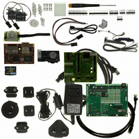
... Getting Started instructions. • xD-Picture Card™ (NAND flash) • A bag of accessory parts for use on the Prototyping Board. • Rabbit 3000 Processor Easy Reference poster. • Registration card. Rabbit and Dynamic C are registered trademarks of Rabbit Semiconductor Inc. Figure 1. RCM3365/RCM3375 Development Kit 6 RabbitCore RCM3365/RCM3375 ...
Page 13
... Rabbit has available a USB Removable Memory Card Reader and a Connector Adapter Board. • USB Removable Memory Card Reader (Part No. 20-101-1104)—allows you to read data from the xD-Picture Card via your PC. • Connector Adapter Board (Part No. 151-0114)—allows you to plug the RCM3365/ RCM3375 whose headers have pitch into header sockets with a 0.1" ...
Page 14
RabbitCore RCM3365/RCM3375 ...
Page 15
This chapter explains how to set up and use the RCM3365/ RCM3375 modules with the accompanying Prototyping Board. NOTE assumed that you have a Development Kit. If you purchased an RCM3365 or RCM3375 module by itself, you will ...
Page 16
Hardware Connections There are three steps to connecting the Prototyping Board for use with Dynamic C and the sample programs: 1. Attach the RCM3365/RCM3375 module to the Prototyping Board. 2. Connect the serial programming cable between the RCM3365/RCM3375 and ...
Page 17
... Figure 3. Connect Serial Programming Cable and Power Supply NOTE: Be sure to use the serial programming cable (part number 101-0542) supplied with this Development Kit—the serial programming cable has blue shrink wrap around the RS-232 converter section located in the middle of the cable. Programming cables with clear or red shrink wrap from other Rabbit kits are not designed to work with RCM3365/ RCM3375 modules ...
Page 18
Programming via Ethernet Option An Ethernet cable connects a RabbitSys-enabled RCM3365 to the PC running Dynamic C with Dynamic C RabbitSys via a DHCP network to download programs and to monitor the RCM3365 module during debugging. Use a straight-through ...
Page 19
Step 3 — Connect Power When all other connections have been made, you can connect power to the Prototyping Board. Connect the wall transformer to jack J1 on the Prototyping Board as shown in Figure 3. Plug in the ...
Page 20
Starting Dynamic C Once the RCM3365/RCM3375 is connected as described in the preceding pages, start Dynamic C by double-clicking on the Dynamic C icon on your desktop or in your menu. Select Code and BIOS in Flash, Run in ...
Page 21
Running Dynamic C via Serial Programming Cable Dynamic C uses the serial port on your PC that you specified during installation. If you are using a USB port to connect your computer to the RCM3365/RCM3375 module, choose Options > ...
Page 22
Running Dynamic C via Ethernet Cables The firmware needed to run RabbitSys has been preloaded on RCM3365 RabbitCore modules sold for use with Dynamic C RabbitSys. The software from the Dynamic C and the Dynamic C RabbitSys CDs must ...
Page 23
Troubleshooting If the rdiscover utility could not find your RCM3365: • Check that your network has a DHCP server, and that the RCM3365 and your PC are connected to the same network. • If you compiled and ran a ...
Page 24
RabbitCore RCM3365/RCM3375 ...
Page 25
R To develop and debug programs for the RCM3365/RCM3375 (and for all other Rabbit hardware), you must install and use Dynamic C. 3.1 Introduction To help familiarize you with the RCM3365 and RCM3375 modules, Dynamic C includes several sample ...
Page 26
Sample Programs Of the many sample programs included with Dynamic C, several are specific to the RCM3365 and the RCM3375. Sample programs illustrating the general operation of the RCM3365/RCM3375, serial communication, and the NAND flash are provided in the ...
Page 27
Use of NAND Flash The following sample programs can be found in the SAMPLES\RCM3360\NANDFlash folder. As you run most of these sample programs, you will be prompted in the Dynamic C STDIO win- dow to select either the soldered-in ...
Page 28
... Now select the IP Address and click on “Properties” to assign an IP address to your computer (this will disable “obtain an IP address automatically”): IP Address : 10.10.6.101 Netmask : 255.255.255.0 Default gateway : 10.10.6.1 4. Click <OK> or <Close> to exit the various dialog boxes. As long as you have not modified the enter the following server address in your Web browser to bring up the Web page served by the sample program ...
Page 29
Hot-Swapping xD-Picture Card The sample programs in this section require that you have installed the Dynamic C FAT File System module, which is included with the RCM3365/RCM3375 Development Kit. Visit our Web site at www.rabbit.com rized distributor for further ...
Page 30
Serial Communication The following sample programs can be found in the —This program demonstrates hardware flow control by configuring • FLOWCONTROL.C Serial Port F for CTS/RTS with serial data coming from TxE (Serial Port E) at 115,200 bps. One ...
Page 31
ASCII string on Serial • SWITCHCHAR.C Ports E and F. It also displays the serial data received from both ports in the window. To set up the Prototyping Board, you will need to ...
Page 32
RabbitNet Sample programs are available for each RabbitNet peripheral card, and can be found in the Dynamic C SAMPLES\RabbitNet in conjunction with the RCM3365/RCM3375 and the Prototyping Board, you need to add the line #use rcm33xx.lib at the beginning ...
Page 33
Chapter 4 describes the hardware components and principal hardware subsystems of the RCM3365/RCM3375 modules. Appendix A, “RCM3365/RCM3375 Specifications,” provides complete physical and electrical specifications. Figure 5 shows the Rabbit-based subsystems designed into the RCM3365/RCM3375. Figure 5. RCM3365/RCM3375 Subsystems User’s Manual ...
Page 34
RCM3365/RCM3375 Inputs and Outputs Figure 6 shows the RCM3365/RCM3375 pinouts for headers J3 and J4. Figure 6. RCM3365/RCM3375 Pinouts The pinouts for the RCM3000, RCM3100, RCM3200, RCM3300/RCM3310, RCM3360/ RCM3370, and RCM3365/RCM3375 are almost compatible, except signals PB0, PC4, and ...
Page 35
Figure 7 shows the use of the Rabbit 3000 microprocessor ports in the RCM3365/ RCM3375 modules. Figure 7. Use of Rabbit 3000 Ports The ports on the Rabbit 3000 microprocessor used in the RCM3365/RCM3375 are config- urable, and so the ...
Page 36
Table 2. RCM3365/RCM3375 Pinout Configurations Pin Pin Name 1 GND 2 STATUS Output (Status) 3–10 PA[7:0] Parallel I/O 11 PF3 Input/Output 12 PF2 Input/Output 13 PF1 Input/Output 14 PF0 Input/Output 15 PC0 Output 16 PC1 Input 17 PC2 Output 18 ...
Page 37
Table 2. RCM3365/RCM3375 Pinout Configurations (continued) Pin Pin Name 1 /RES Reset output 2 PB0 Input/Output 3 PB2 Input/Output 4 PB3 Input/Output 5 PB4 Input/Output 6 PB5 Input/Output 7 PB6 Input/Output 8 PB7 Input/Output 9 PF4 Input/Output 10 PF5 Input/Output ...
Page 38
Table 2. RCM3365/RCM3375 Pinout Configurations (continued) Pin Pin Name 20 PG7 Input/Output 21 PG6 Input/Output 22 PG5 Input/Output 23 PG4 Input/Output 24 /IOWR Output 25 /IORD Output (0,0)—start executing at address zero (0,1)—cold boot from slave port (1,0)—cold boot from ...
Page 39
Memory I/O Interface The Rabbit 3000 address lines (A0–A18) and all the data lines (D0–D7) are routed internally to the onboard flash memory and SRAM chips. I/0 write (/IOWR) and I/0 read (/IORD) are available for interfacing to external ...
Page 40
Serial Communication The RCM3365/RCM3375 does not have any serial transceivers directly on the board. However, a serial interface may be incorporated into the board the RCM3365/RCM3375 is mounted on. For example, the Prototyping Board has RS-232 and RS-485 transceiver ...
Page 41
Serial Programming Port The RCM3365/RCM3375 is programmed either through the serial programming port, which is accessed using header J1 or through the Ethernet jack. The RabbitLink may be used to provide a serial connection via the RabbitLink’s Ethernet jack. ...
Page 42
Serial Programming Cable The programming cable is used to connect the serial programming port of the RCM3365/ RCM3375 serial COM port. The programming cable converts the RS-232 voltage levels used by the PC serial port to ...
Page 43
A program “runs” in either mode, but can only be downloaded and debugged when the RCM3365/RCM3375 is in the Program Mode. Refer to the Rabbit 3000 Microprocessor User’s Manual gramming port. 4.3.2 Standalone Operation of the RCM3365/RCM3375 The RCM3365/RCM3375 must ...
Page 44
Memory 4.4.1 SRAM RCM3365/RCM3375 boards have 512K of program-execution fast SRAM at U11. The program-execution SRAM is not battery-backed. There are 512K of battery-backed data SRAM installed at U10. 4.4.2 Flash EPROM RCM3365/RCM3375 boards also have 512K of flash ...
Page 45
Figure 10 shows how to insert or remove the the , take care to avoid touching the electrical contacts on the bottom of the xD-Picture Card card to prevent electrostatic discharge damage to the card and to keep any moisture ...
Page 46
Other Hardware 4.5.1 Clock Doubler The RCM3365/RCM33610 takes advantage of the Rabbit 3000 microprocessor’s internal clock doubler. A built-in clock doubler allows half-frequency crystals to be used to reduce radiated emissions. The 44.2 MHz frequency specified for the RCM3365/RCM3375 ...
Page 47
Dynamic integrated development system for writing embedded software. It runs on an IBM-compatible PC and is designed for use with Rabbit controllers and other controllers based on the Rabbit microprocessor. Chapter 5 describes the libraries and function ...
Page 48
Dynamic C release prior to v. 9.60 under Win- dows Vista. Programs can be downloaded at baud rates 460,800 bps after the pro- gram compiles. Dynamic C has a ...
Page 49
Developing Programs Remotely with Dynamic C Dynamic integrated development environment that allows you to edit, compile, and debug your programs. Dynamic C has the ability to allow programming over the Internet or local Ethernet. This is ...
Page 50
Dynamic C Functions 5.2.1 Digital I/O The RCM3365/RCM3375 was designed to interface with other systems, and so there are no drivers written specifically for the I/O. The general Dynamic C read and write func- tions allow you to customize ...
Page 51
Serial Communication Drivers Library files included with Dynamic C provide a full range of serial communications sup- port. The library provides a set of circular-buffer-based serial functions. The RS232.LIB library provides packet-based serial functions where packets can be delimited ...
Page 52
Prototyping Board Functions The functions described in this section are for use with the Prototyping Board features. The source code is in the Dynamic C need to modify it for your own board design. The library is supported by ...
Page 53
Digital I/O int digIn(int channel); Reads the input state of inputs on Prototyping Board headers J5 and J6. Do not use this function if you configure these pins for alternate use after brdInit() is called. PARAMETERS channels is the ...
Page 54
Switches, LEDs, and Relay int switchIn(int swin); Reads the state of a switch input. PARAMETERS swin is the switch input to read: 2—S2 3—S3 RETURN VALUE State of the switch input open 0 = closed SEE ALSO ...
Page 55
Sets the position for the relay common contact. The default position is for normally closed contacts. PARAMETERS relay is the one relay (1) value is the value used to connect the relay common contact: 0 ...
Page 56
RabbitNet Port The function calls described in this section are used to configure the RabbitNet port on the Prototyping Board for use with RabbitNet peripheral cards. The user’s manual for the spe- cific peripheral card you are using contains ...
Page 57
Deactivates the RCM3365/RCM3375 RabbitNet port as a clocked serial port. This call is also used by rn_init(). PARAMETERS portnum = 0 RETURN VALUE None void rn_sp_enable(int portnum); This is a macro that enables or asserts the RCM3365/RCM3375 ...
Page 58
Upgrading Dynamic C Dynamic C patches that focus on bug fixes are available from time to time. Check the Web site www.rabbit.com/support/ 5.3.1 Extras Dynamic C installations are designed for use with the board they are included with, and ...
Page 59
U 6.1 TCP/IP Connections Programming and development can be done with the RCM3365/RCM3375 modules with- out connecting the Ethernet port to a network. However, if you will be running the sample programs that use the Ethernet capability or will ...
Page 60
Now you should be able to make your connections. 1. Connect the AC adapter and the serial programming cable as shown in Chapter 2, “Get- ting Started.” 2. Ethernet Connections There are four options for connecting the RCM3365/RCM3375 module to ...
Page 61
TCP/IP Primer on IP Addresses Obtaining IP addresses to interact over an existing, operating, network can involve a num- ber of complications, and must usually be done with cooperation from your ISP and/or network systems administrator. For this reason, ...
Page 62
Firewall T1 in Adapter Ethernet Typical Corporate Network If your system administrator can give you an Ethernet cable along with its IP address, the netmask and the gateway address, then you may be able to run the sample programs with- ...
Page 63
IP Addresses Explained IP (Internet Protocol) addresses are expressed as 4 decimal numbers separated by periods, for example: 216.103.126.155 10.1.1.6 Each decimal number must be between 0 and 255. The total IP address is a 32-bit number consisting of ...
Page 64
How IP Addresses are Used The actual hardware connection via an Ethernet uses Ethernet adapter addresses (also called MAC addresses). These are 48-bit addresses and are unique for every Ethernet adapter manufactured. In order to send a packet to ...
Page 65
Dynamically Assigned Internet Addresses In many instances, devices on a network do not have fixed IP addresses. This is the case when, for example, you are assigned an IP address dynamically by your dial-up Internet service provider (ISP) or ...
Page 66
Placing Your Device on the Network In many corporate settings, users are isolated from the Internet by a firewall and/or a proxy server. These devices attempt to secure the company from unauthorized network traffic, and usually work by disallowing ...
Page 67
Running TCP/IP Sample Programs We have provided a number of sample programs demonstrating various uses of TCP/IP for networking embedded systems. These programs require you to connect your PC and the RCM3365/RCM3375 board together on the same network. This ...
Page 68
How to Set IP Addresses in the Sample Programs With the introduction of Dynamic C 7.30 we have taken steps to make it easier to run many of our sample programs. You will see a Dynamic C to select ...
Page 69
... NOTE: Your network interface card will likely have a different name. 3. Now select the IP Address click on “Properties” to assign an IP address to your computer (this will disable “obtain an IP address automatically”): IP Address : 10.10.6.101 Netmask : 255.255.255.0 Default gateway : 10.10.6.1 4. Click or to exit the various dialog boxes. ...
Page 70
... DOS window and running the pingme program: ping 10.10.6.101 or by Start > Run and typing the entry ping 10.10.6.101 Notice that the yellow light flashes on the RCM3365/RCM3375 module while the ACT ping is taking place, and indicates the transfer of data. The ping routine will ping the board four times and write a summary message on the screen describing the operation ...
Page 71
ICMP by pinging a remote host. It will flash • PINGLED.C LEDs DS3 and DS4 on the Prototyping Board when a ping is sent and received. —This program demonstrates using the SMTP library to send an e-mail ...
Page 72
RabbitCore RCM3365/RCM3375 ...
Page 73
A PPENDIX Appendix A provides the specifications for the RCM3365/ RCM3375, and describes the conformal coating. User’s Manual A. RCM3365/RCM3375 S PECIFICATIONS 67 ...
Page 74
A.1 Electrical and Mechanical Characteristics Figure A-1 shows the mechanical dimensions for the RCM3365/RCM3375. Figure A-1. RCM3365/RCM3375 Dimensions NOTE: All measurements are in inches followed by millimeters enclosed in parentheses. All dimensions have a manufacturing tolerance of ±0.01" (0.25 mm). ...
Page 75
It is recommended that you allow for an “exclusion zone” of 0.04" (1 mm) around the RCM3365/RCM3375 in all directions when the RCM3365/RCM3375 is incorporated into an assembly that includes other printed circuit boards. An “exclusion zone” of 0.08" (2 ...
Page 76
Table A-1 lists the electrical, mechanical, and environmental specifications for the RCM3365/ RCM3375. Table A-1. RabbitCore RCM3365/RCM3375 Specifications Parameter Microprocessor EMI Reduction Ethernet Port SRAM Flash Memory (program) Flash Memory (mass data storage) LED Indicators Backup Battery General-Purpose I/O Additional ...
Page 77
Table A-1. RabbitCore RCM3365/RCM3375 Specifications (continued) Parameter Watchdog/ Supervisor Pulse-Width Modulators 2-channel input capture can be used to time input signals from Input Capture various port pins Quadrature 2-channel quadrature decoder accepts inputs from external Decoder incremental encoder modules Power ...
Page 78
A.1.1 Headers The RCM3365/RCM3375 uses headers at J3 and J4 for physical connection to other boards. J3 and J4 are 2 × 17 SMT headers with pin spacing. J1, the programming port × 5 ...
Page 79
A.2 Bus Loading You must pay careful attention to bus loading when designing an interface to the RCM3365/RCM3375. This section provides bus loading information for external devices. Table A-2 lists the capacitance for the various RCM3365/RCM3375 I/O ports. Table A-2. ...
Page 80
Figure A-4 shows a typical timing diagram for the Rabbit 3000 microprocessor external I/O read and write cycles. Figure A-4. I/O Read and Write Cycles—No Extra Wait States NOTE: /IOCSx can be programmed to be active low (default) or active ...
Page 81
Table A-4 lists the delays in gross memory access time at 3.3 V. Table A-4. Data and Clock Delays VIN ±10%, Temp, -40°C–+85°C (maximum) Clock to Address Output Delay (ns) VIN 3 The measurements ...
Page 82
A.3 Rabbit 3000 DC Characteristics Table A-5. Rabbit 3000 Absolute Maximum Ratings Symbol T Operating Temperature A T Storage Temperature S Maximum Input Voltage: • Oscillator Buffer Input • 5-V-tolerant I/O V Maximum Operating Voltage DD Stresses beyond those listed ...
Page 83
A.4 I/O Buffer Sourcing and Sinking Limit Unless otherwise specified, the Rabbit I/O buffers are capable of sourcing and sinking 6 current per pin at full AC switching speed. Full AC switching assumes a 22.1 MHz CPU clock ...
Page 84
A.5 Jumper Configurations Figure A-5 shows the jumper locations used to configure the various RCM3365/ RCM3375 options. The black square indicates pin 1. Figure A-5. Location of RCM3365/RCM3375 Configurable Positions 78 RabbitCore RCM3365/RCM3375 ...
Page 85
Table A-8 lists the configuration options. Table A-8. RCM3365/RCM3375 Jumper Configurations Header Description JP2 Flash Memory Bank Select JP3 Data SRAM Size Ethernet or I/O Output JP4 on Header J3 Ethernet or I/O Output JP5 on Header J3 Ethernet or ...
Page 86
A.6 Conformal Coating The areas around the 32 kHz real-time clock crystal oscillator have had the Dow Corning silicone-based 1-2620 conformal coating applied. The conformally coated area is shown in Figure A-6. The conformal coating protects these high-impedance circuits from ...
Page 87
A PPENDIX Appendix B describes the features and accessories of the Proto- typing Board. User’s Manual B. P ROTOTYPING B OARD 81 ...
Page 88
B.1 Introduction The Prototyping Board included in the Development Kit makes it easy to connect an RCM3365/RCM3375 module to a power supply and a PC workstation for development. It also provides some basic I/O peripherals (RS-232, RS-485, a relay, LEDs, ...
Page 89
B.1.1 Prototyping Board Features —A power-supply jack and a 3-pin header are provided for con- Power Connection • nection to the power supply. Note that the 3-pin header is symmetrical, with both outer pins connected to ground and the center ...
Page 90
Module Extension Headers • module is duplicated at headers J8 and J9. Developers can solder wires directly into the appropriate holes, or, for more flexible development, 2 × 17 header strips with a 0.1" pitch can be soldered into place. ...
Page 91
B.2 Mechanical Dimensions and Layout Figure B-2 shows the mechanical dimensions and layout for the Prototyping Board. Figure B-2. Prototyping Board Dimensions NOTE: All measurements are in inches followed by millimeters enclosed in parentheses. User’s Manual 85 ...
Page 92
Table B-1 lists the electrical, mechanical, and environmental specifications for the Proto- typing Board. Table B-1. Prototyping Board Specifications Parameter Board Size Operating Temperature Humidity Input Voltage Maximum Current Draw (including user-added circuits) Backup Battery Digital Inputs Digital Outputs Relay ...
Page 93
B.3 Power Supply The RCM3365/RCM3375 requires a regulated 3. 3. power source to oper- ate. Depending on the amount of current required by the application, different regulators can be used to supply this voltage. The Prototyping ...
Page 94
B.4 Using the Prototyping Board The Prototyping Board is actually both a demonstration board and a prototyping board demonstration board, it can be used with the sample programs to demonstrate the func- tionality of the RCM3365/RCM3375 right out ...
Page 95
The Prototyping Board comes with the basic components necessary to demonstrate the operation of the RCM3365/RCM3375. Four user LEDs (DS3–DS6) are connected to alternate I/O bus pins PA0–PA3 pins of the RCM3365/RCM3375 module via U8, and may be driven as ...
Page 96
B.4.2 Digital I/O B.4.2.1 Digital Inputs The Prototyping Board has four digital inputs, IN0–IN3, each of which is protected over a range of – +36 V. The inputs are pulled shown in Figure ...
Page 97
B.4.3 CMOS Digital Outputs If the stepper-motor option is not used, eight CMOS-level digital outputs are available at J10, and can each handle mA. B.4.4 Sinking Digital Outputs Four sinking digital outputs shared with LEDs DS3–DS6 are ...
Page 98
B.4.6 Serial Communication The Prototyping Board allows you to access up to five of the serial ports from the RCM3365/RCM3375 module. Table B-2 summarizes the configuration options. Table B-2. Prototyping Board Serial Port Configurations Serial Port Signal Header B J9 ...
Page 99
B.4.6.1 RS-232 RS-232 serial communication on the Prototyping Board is supported by an RS-232 trans- ceiver installed at U9. This transceiver provides the voltage output, slew rate, and input voltage immunity required to meet the RS-232 serial communication protocol. Basically, ...
Page 100
B.4.6.2 RS-485 The Prototyping Board has one RS-485 serial channel, which is connected to the Rabbit 3000 Serial Port C through an RS-485 transceiver. The half-duplex communication uses an output from PD7 on the Rabbit 3000 to control the transmit ...
Page 101
The Prototyping Board comes with a 220 Ω termination resistor and two 681 Ω bias resis- tors installed and enabled with jumpers across pins 1–2 and 5–6 on header JP5, as shown in Figure B-9. Figure B-9. RS-485 Termination and ...
Page 102
B.4.8 Other Prototyping Board Modules An optional LCD/keypad module is available that can be mounted on the Prototyping Board. The signals on headers LCD1JB and LCD1JC will be available only if the LCD/ keypad module is installed. Refer to Appendix ...
Page 103
Figure B-11 shows the stepper-motor driver circuit. Figure B-11. Stepper-Motor Driver Circuit The stepper motor(s) can be powered either from the onboard power supply or from an external power based on the jumper settings on headers JP1 and JP2. Table ...
Page 104
B.5 Prototyping Board Jumper Configurations Figure B-12 shows the header locations used to configure the various Prototyping Board options via jumpers. Figure B-12. Location of Prototyping Board Configurable Positions 98 RabbitCore RCM3365/RCM3375 ...
Page 105
Table B-4 lists the configuration options using jumpers. Table B-4. Prototyping Board Jumper Configurations Header Description Stepper Motor Power-Supply JP1 Options (U2) Stepper Motor Power-Supply JP2 Options (U3) JP3 PF0 Option RCM3365/RCM3375 Power JP4 Supply RS-485 Bias and Termination JP5 ...
Page 106
B.6 Use of Rabbit 3000 Parallel Ports Table B-5 lists the Rabbit 3000 parallel ports and their use for the Prototyping Board. Table B-5. Prototyping Board Use of Rabbit 3000 Parallel Ports Port I/O PA0–PA3 Data Bus PA4 Data Bus ...
Page 107
... RXF RS-232 Motor driver A enable Motor driver B enable TXE RS-232 Serial Port E RXE RS-232 Initial State High (disabled) High High Low (disabled) High High High (RS-232 disabled) High (RS-232 disabled) High (disabled) High (disabled) High (RS-232 disabled) High (RS-232 disabled) 101 ...
Page 108
RabbitCore RCM3365/RCM3375 ...
Page 109
A PPENDIX An optional LCD/keypad is available for the Prototyping Board. Appendix C describes the LCD/keypad and provides the soft- ware function calls to make full use of the LCD/keypad. C.1 Specifications Two optional LCD/keypad modules—with or without a panel-mounted ...
Page 110
Mounting hardware and (24") extension cable are also available for the LCD/ keypad module through your sales representative or authorized distributor. Table C-1 lists the electrical, mechanical, and environmental specifications for the LCD/ keypad module. Table C-1. ...
Page 111
C.2 Contrast Adjustments for All Boards Starting in 2005, LCD/keypad modules were factory-configured to optimize their contrast based on the voltage of the system they would be used in. Be sure to select a KDU3V LCD/keypad module for use with ...
Page 112
C.3 Keypad Labeling The keypad may be labeled according to your needs. A template is provided in Figure C-4 to allow you to design your own keypad label insert. To replace the keypad legend, remove the old legend and insert ...
Page 113
C.4 Header Pinouts Figure C-6 shows the pinouts for the LCD/keypad module. Figure C-6. LCD/Keypad Module Pinouts C.4.1 I/O Address Assignments The LCD and keypad on the LCD/keypad module are addressed by the /CS strobe as explained in Table C-2. ...
Page 114
C.5 Mounting LCD/Keypad Module on the Prototyping Board Install the LCD/keypad module on header sockets LCD1JA, LCD1JB, and LCD1JC of the Prototyping Board as shown in Figure C-7. Be careful to align the pins over the headers, and do not ...
Page 115
C.6 Bezel-Mount Installation This section describes and illustrates how to bezel-mount the LCD/keypad module designed for remote installation. Follow these steps for bezel-mount installation. 1. Cut mounting holes in the mounting panel in accordance with the recommended dimen- sions in ...
Page 116
Fasten the unit with the four 4-40 screws and washers included with the LCD/keypad module. If your panel is thick, use a 4-40 screw that is approximately 3/16" (5 mm) longer than the thickness of the panel. Figure C-9. ...
Page 117
C.6.1 Connect the LCD/Keypad Module to Your Prototyping Board The LCD/keypad module can be located as far as 2 ft. (60 cm) away from the Prototyping Board, and is connected via a ribbon cable as shown in Figure C-10. Figure ...
Page 118
C.7 Sample Programs Sample programs illustrating the use of the LCD/keypad module with the Prototyping Board are provided in the SAMPLES\RCM3360\LCD_KEYPAD These sample programs use the external I/O bus on the Rabbit 3000 chip, and so the line is already ...
Page 119
C.8 LCD/Keypad Module Function Calls When mounted on the Prototyping Board, the LCD/keypad module uses the external I/O bus on the Rabbit 3000 chip. Remember to add the line #define PORTA_AUX_IO to the beginning of any programs using the external ...
Page 120
C.8.3 LCD Display The functions used to control the LCD display are contained in the located in the Dynamic C LIB\DISPLAYS\GRAPHIC nates on the display screen are specified, x can range from 0 to 121, and y can range from ...
Page 121
Sets display contrast. NOTE: This function is not used with the LCD/keypad module since the support circuits are not available on the LCD/keypad module. void glFillScreen(char pattern); Fills the LCD display screen with a pattern. PARAMETER The ...
Page 122
Plots the outline of a polygon in the LCD page buffer, and on the LCD if the buffer is unlocked. Any portion of the polygon that is outside the LCD display area will be clipped. ...
Page 123
Fills a polygon in the LCD page buffer and on the LCD screen if the buffer is unlocked. Any portion of the polygon that is outside the LCD display area will be clipped. If fewer ...
Page 124
Draws a filled circle in the LCD page buffer and on the LCD if the buffer is unlocked. Any portion of the circle that is outside the LCD display area will be clipped. ...
Page 125
Returns the xmem address of the character from the specified font set. PARAMETERS *pInfo is the xmem address of the bitmap font set. letter is an ASCII character. RETURN VALUE xmem address of bitmap ...
Page 126
Gets the current glPrintf() printing step direction. Each step direction is independent of the other, and is treated as an 8-bit signed value. The actual step increments depends on the height and width of the font being displayed, ...
Page 127
Prints a formatted string (much like printf) on the LCD screen. Only the character codes that exist in the font set are printed, all others are skipped. For example, '\b', ...
Page 128
Checks the LCD screen locking counter. The contents of the LCD buffer are transferred to the LCD if the counter is zero. RETURN VALUE None. SEE ALSO glBuffUnlock, glBuffLock, _glSwapData that you are using) void glSetBrushType(int type); Sets ...
Page 129
Draws a line in the LCD buffer, and on the LCD if the buffer is unlocked. Any portion of the line that is beyond the LCD display area will be clipped. ...
Page 130
Scrolls byte-aligned window up one pixel, bottom column is filled by current pixel type (color). PARAMETERS left is the top left corner of bitmap, must be evenly divisible by 8, otherwise ...
Page 131
Scrolls right or left, within the defined window by x number of pixels. The opposite edge of the scrolled window will be filled in with white pixels. The window ...
Page 132
Scrolls up or down, within the defined window by x number of pixels. The opposite edge of the scrolled window will be filled in with white pixels. The window ...
Page 133
Draws bitmap in the specified space. The data for the bitmap are stored in xmem. This function is like glXPutBitmap, except that it is faster. The restriction is ...
Page 134
TextGotoXY(windowFrame *window, int col, int row); Sets the cursor location to display the next character. The display location is based on the height and width of the character to be displayed. NOTE: Execute the TextWindowFrame PARAMETERS *window is a ...
Page 135
TextPutChar(struct windowFrame *window, char ch); Displays a character on the display where the cursor is currently pointing. If any portion of a bitmap character is outside the LCD display area, the character will not be displayed. The cursor increments ...
Page 136
C.8.4 Keypad The functions used to control the keypad are contained in the located in the Dynamic C KEYPADS void keyInit(void); Initializes keypad process RETURN VALUE None. SEE ALSO brdInit void keyConfig(char cRaw, char cPress, char cRelease, char cCntHold, char ...
Page 137
How many times to repeat after low speed repeat None. RETURN VALUE None. SEE ALSO keyProcess, keyGet, keypadDef void keyProcess(void); Scans and processes ...
Page 138
Configures the physical layout of the keypad with the default ASCII return key codes. Keypad physical mapping ['L'] ['U'] ['–'] where 'D' represents Down Scroll 'U' represents Up Scroll 'R' represents Right ...
Page 139
A Appendix D provides information on the current requirements of the RCM3365/RCM3375 modules, and includes some background on the reset generator. D.1 Power Supplies Power is supplied from the motherboard to which the RCM3365/RCM3375 is connected via header J4. The ...
Page 140
A lithium battery with a nominal voltage and a minimum capacity of 165 mA·h is recommended. A lithium battery is strongly recommended because of its nearly constant nominal voltage over most of its life. The drain on ...
Page 141
D.1.3 Reset Generator The RCM3365/RCM3375 uses a reset generator to reset the Rabbit 3000 microprocessor when the voltage drops below the voltage necessary for reliable operation. The reset occurs between 2.85 V and 3.00 V, typically 2.93 V. The RCM3365/RCM3375 ...
Page 142
RabbitCore RCM3365/RCM3375 ...
Page 143
A PPENDIX E THERNET A RabbitSys-enabled RCM3365 module can also be pro- grammed with a CAT5/6 Ethernet crossover cable connecting the RCM3365 module directly notebook. This appen- dix describes the connection and how to set up ...
Page 144
E.1 Load TCP/IP Parameters to the RCM3365 Module 1. Connect the 10-pin PROG the RCM3365 module as described in Section 2.2.2. (Do not use the 2. Use the File menu to open the sample program the Dynamic C SAMPLES\RABBITSYS run ...
Page 145
E.2 Load TCP/IP Parameters to the PC, Notebook, or Workstation If the PC, notebook, or workstation is connected to a network, disconnect it from the network. Check with your administrator if you are unable to change the settings as described ...
Page 146
... IP Address , or select TCP/IP Specify an IP Address and click on “Properties” to fill in the fol- lowing fields: IP Address : 10.10.6.101 Netmask : 255.255.255.0 Default gateway : 10.10.6.1 TIP: If you are using a PC that is nor- mally on a network, you will have dis- connected the PC from that network. ...
Page 147
E.3 Run a Program You are now ready to run a sample program or develop a new application. Review these steps to check your Dynamic C RabbitSys setup before you run a program. 1. Set the compiler to run the ...
Page 148
RabbitCore RCM3365/RCM3375 ...
Page 149
F.1 General RabbitNet Description RabbitNet is a high-speed synchronous protocol developed by Rabbit to connect periph- eral cards to a master and to allow them to communicate with each other. F.1.1 RabbitNet Connections All RabbitNet connections are made point to ...
Page 150
Use a straight-through Ethernet cable to connect the master to slave peripheral cards, unless you are using a device such as the OP7200 that could be used either as a master or a slave. In this case you would use ...
Page 151
F.2 Physical Implementation There are four signaling functions associated with a RabbitNet connection. From the mas- ter’s point of view, the transmit function carries information and commands to the periph- eral card. The receive function is used to read back ...
Page 152
F.3 Function Calls The function calls described in this section are used with all RabbitNet peripheral cards, and are available in the RNET.LIB int rn_init(char portflag, char servicetype); Resets, initializes, or disables a specified RabbitNet port on the master single-board ...
Page 153
Locates the first active device that matches the search criteria. PARAMETER srch is the search criteria structure rn_search: unsigned int flags; unsigned int ports; char productid; char productrev; char coderev; long serialnum; Use a maximum of 3 ...
Page 154
Writes a string to the specified device and register. Waits for results. mation to determine that the peripheral card is connected to a master. PARAMETERS handle is an address index to ...
Page 155
Sends a reset sequence to the specified peripheral card. The reset takes approximately 25 ms before the peripheral card will once again execute the application. Allow 1.5 seconds after the reset has completed before accessing ...
Page 156
Enables the hardware and/or software watchdog timers on a peripheral card. The software on the periph- eral card will keep the hardware watchdog timer updated, but will hard reset if the time expires. The hardware ...
Page 157
Reads the status of which reset occurred and whether any watchdogs are enabled. PARAMETERS handle is an address index to device information. Use rn_device() or rn_find() to establish the handle. retdata is a pointer to ...
Page 158
F.3.1 Status Byte Unless otherwise specified, functions returning a status byte will have the following format for each designated bit × × × × * Use the function rn_comm_status() to determine which error occurred. † Use ...
Page 159
Symbols /IOWR loading .............................. 32 A accessories Connector Adapter Board ... 7 USB Removable Memory Card Reader .................... 7 additional information online documentation .......... 7 B battery backup circuit .............................. 134 external battery connec- tions ............................ 133 reset generator ................. ...
Page 160
J jumper configurations Prototyping Board JP1 (stepper motor power supply) ........................99 JP2 (stepper motor power supply) ........................99 JP3 (quadrature decoder/ serial flash) .................99 JP4 (RCM3365/RCM3375 power supply) .............99 JP5 (RS-485 bias and termi- nation resistors) ....95, 99 stepper motor power ...
Page 161
Prototyping Board ................. 82 adding components ........... 89 dimensions ........................ 85 expansion area ................... 83 features ........................ 82, 83 jumper configurations ....... 99 jumper locations ................ 98 mounting RCM3365/ RCM3375 ..................... 10 power supply ..................... 87 prototyping area ................ 89 ...
Page 162
I/O bus .................44 I/O drivers .........................44 libraries LCD122KEY7.LIB .....113 NAND flash ...................45 PACKET.LIB ................45 RCM33XX.LIB .............46 RN_CFG_RCM33.LIB .46 RNET.LIB ...................146 RS232.LIB .....................45 TCP/IP ...........................45 NAND flash drivers ..........45 serial communication drivers ........................................45 TCP/IP drivers ...................45 specifications .........................67 ...
Page 163
RCM3365/RCM3375 Schematic www.rabbit.com/documentation/schemat/090-0214.pdf 090-0188 Prototyping Board Schematic www.rabbit.com/documentation/schemat/090-0188.pdf 090-0156 LCD/Keypad Module Schematic www.rabbit.com/documentation/schemat/090-0156.pdf 090-0128 Serial Programming Cable Schematic www.rabbitsemiconductor.com/documentation/schemat/090-0128.pdf You may use the URL information provided above to access the latest schematics directly. User’s Manual S CHEMATICS 157 ...
Page 164
...