AT91SAM9M10-G45-EK Atmel, AT91SAM9M10-G45-EK Datasheet - Page 1162
AT91SAM9M10-G45-EK
Manufacturer Part Number
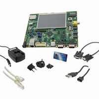
AT91SAM9M10-G45-EK
Description
KIT EVAL FOR AT91SAMG45/9M10
Manufacturer
Atmel
Series
AT91SAM Smart ARMr
Type
MCUr
Specifications of AT91SAM9M10-G45-EK
Contents
Board, Cables, Power Supply
Processor To Be Evaluated
AT91SAM9M10
Processor Series
AT91SAM9
Data Bus Width
32 bit
Interface Type
RS-232, Ethernet, USB, JTAG
Operating Supply Voltage
5 V
Silicon Manufacturer
Atmel
Core Architecture
AVR
Kit Contents
Board
Features
Two High Speed USB Hosts, LCD TFT Display
Svhc
No SVHC (15-Dec-2010)
Mcu Supported Families
AT91SAM9M10,
Rohs Compliant
Yes
For Use With/related Products
AT91SAM9M10
Lead Free Status / RoHS Status
Lead free / RoHS Compliant
Available stocks
Company
Part Number
Manufacturer
Quantity
Price
Company:

Part Number:
AT91SAM9M10-G45-EK
Manufacturer:
INFINEON
Quantity:
10 000
Company:
Part Number:
AT91SAM9M10-G45-EK
Manufacturer:
Atmel
Quantity:
135


46.5
Table 46-9.
6355B–ATARM–21-Jun-10
0x0000
0x0004
0x0008
0x000C
0x0010
0x0014
0x0018
0x001C
0x0020
0x0024
0x0028
0x002C
0x0030
0x0034
0x0038
0x003C
0x0040
0x0044
Offset
Video Decoder (VDEC) User Interface
Register
ID Register
Decoder Interrupt Register
Decoder Device Configuration Register
Decoder Control Register 0
Decoder Control Register 1
Decoder Control Register 2
Decoder Control Register 3
Decoder Control Register 4
Decoder Control Register 5
Decoder Control Register 6
Base Address for Differential Motion Vector
Decoder Control Register 7
Decoded Picture Base Address
Reference Picture Index 0 Base Address
Reference Picture Index 1 Base Address
Reference Picture Index 2 Base Address
Reference Picture Index 3 Base Address
RLC/VLC Data Base Address
Video Decoder Register Mapping (All Decoders)
The VDEC User interface is split into two interfaces.
Table 46-8.
Note:
Decoder Mode
H264
MPEG4
H263
JPEG
VC1
MPEG2
MPEG1
• One that concerns Post Processor and is common to all Decoder Modes, described by Video
• One in which registers and fields depend on the Decoder Mode used. For best readability this
Post Processor Register Mapping.
document describes one Register Mapping for each Decoder Mode. The relations are given
in
Table
The decoder mode is defined by the field DEC_MODE in Decoder Control Register 0.
46-8.
Register Mapping vs. Decoder Mode
Refer to the following Register Mapping
Video Decoder Register Mapping (H264)
Video Decoder Register Mapping (MPEG4H263)
Video Decoder Register Mapping (MPEG4H263)
Video Decoder Register Mapping (JPEG)
Video Decoder Register Mapping (VC1)
Video Decoder Register Mapping (MPEG2MPEG1)
Video Decoder Register Mapping (MPEG2MPEG1)
(1)
X
X
X
X
X
X
X
X
X
X
X
X
X
X
X
X
X
X
(2)
X
X
X
X
X
X
X
–
X
X
X
X
X
X
X
X
X
–
(3)
X
X
X
X
X
X
X
–
–
–
–
–
X
X
X
X
X
X
(4)
X
X
X
X
X
X
X
X
X
X
X
X
X
X
X
X
X
X
(5)
X
X
X
X
X
X
X
–
–
–
–
–
X
X
X
X
X
X
Name
VDEC_IDR
VDEC_DIR
VDEC_DDCR
VDEC_CTLR0
VDEC_CTLR1
VDEC_CTLR2
VDEC_CTLR3
VDEC_CTLR4
VDEC_CTLR5
VDEC_CTLR6
VDEC_DMVBA
VDEC_CTLR7
VDEC_RLCVLCBA
VDEC_PICTBA
VDEC_PIDXBA0
VDEC_PIDXBA1
VDEC_PIDXBA2
VDEC_PIDXBA3
AT91SAM9M10
Read-only
Read-write
Read-write
Read-write
Read-write
Read-write
Read-write
Read-write
Read-write
Read-write
Read-write
Read-write
Read-write
Read-write
Read-write
Read-write
Read-write
Read-write
Access
0x81701000
0x00000000
0x00000400
0x00000000
0x00000000
0x00000000
0x00000000
0x00000000
0x00000000
0x00000000
0x00000000
0x00000000
0x00000000
0x00000000
0x00000000
0x00000000
0x00000000
0x00000000
Reset
1162
Related parts for AT91SAM9M10-G45-EK
Image
Part Number
Description
Manufacturer
Datasheet
Request
R

Part Number:
Description:
KIT EVAL FOR AT91SAM9M10
Manufacturer:
Atmel
Datasheet:

Part Number:
Description:
IC MCU 16/32BIT ARM9 324TFBGA
Manufacturer:
Atmel
Datasheet:

Part Number:
Description:
At91 Arm Thumb-based Microcontrollers
Manufacturer:
ATMEL Corporation
Datasheet:

Part Number:
Description:
MCU, MPU & DSP Development Tools KICKSTART KIT FOR AT91SAM9 PLUS
Manufacturer:
IAR Systems

Part Number:
Description:
DEV KIT FOR AVR/AVR32
Manufacturer:
Atmel
Datasheet:
Part Number:
Description:
INTERVAL AND WIPE/WASH WIPER CONTROL IC WITH DELAY
Manufacturer:
ATMEL Corporation
Datasheet:
Part Number:
Description:
Low-Voltage Voice-Switched IC for Hands-Free Operation
Manufacturer:
ATMEL Corporation
Datasheet:
Part Number:
Description:
MONOLITHIC INTEGRATED FEATUREPHONE CIRCUIT
Manufacturer:
ATMEL Corporation
Datasheet:
Part Number:
Description:
AM-FM Receiver IC U4255BM-M
Manufacturer:
ATMEL Corporation
Datasheet:
Part Number:
Description:
Monolithic Integrated Feature Phone Circuit
Manufacturer:
ATMEL Corporation
Datasheet:
Part Number:
Description:
Multistandard Video-IF and Quasi Parallel Sound Processing
Manufacturer:
ATMEL Corporation
Datasheet:
Part Number:
Description:
High-performance EE PLD
Manufacturer:
ATMEL Corporation
Datasheet: