TOOLSTICK540DC Silicon Laboratories Inc, TOOLSTICK540DC Datasheet - Page 211
TOOLSTICK540DC
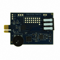
Manufacturer Part Number
TOOLSTICK540DC
Description
DAUGHTER CARD TOOLSTICK F540
Manufacturer
Silicon Laboratories Inc
Series
ToolStickr
Type
MCUr
Datasheets
1.TOOLSTICK540DC.pdf
(274 pages)
2.TOOLSTICK540DC.pdf
(16 pages)
3.TOOLSTICK540DC.pdf
(12 pages)
Specifications of TOOLSTICK540DC
Contents
Daughter Card
Processor To Be Evaluated
C8051F54x
Processor Series
C8051F54x
Interface Type
USB
Operating Supply Voltage
2.7 V to 3.6 V
Lead Free Status / RoHS Status
Lead free / RoHS Compliant
For Use With/related Products
C8051F54x
For Use With
336-1345 - TOOLSTICK BASE ADAPTER336-1182 - ADAPTER USB DEBUG FOR C8051FXXX
Lead Free Status / Rohs Status
Lead free / RoHS Compliant
Other names
336-1717


SFR Definition 21.2. SMOD0: Serial Port 0 Control
SFR Address = 0xA9; SFR Page = 0x00
Name
Reset
Bit
6:5 S0PT[1:0] Parity Type Select Bits.
3:2 S0DL[1:0] Data Length.
Type
7
4
1
0
Bit
MCE0
Name
XBE0
SBL0
PE0
MCE0
R/W
7
0
Multiprocessor Communication Enable.
0: RI0 will be activated if stop bit(s) are 1.
1: RI0 will be activated if stop bit(s) and extra bit are 1. Extra bit must be enabled using
XBE0.
00: Odd Parity
01: Even Parity
10: Mark Parity
11: Space Parity.
Parity Enable.
This bit enables hardware parity generation and checking. The parity type is selected
by bits S0PT[1:0] when parity is enabled.
0: Hardware parity is disabled.
1: Hardware parity is enabled.
00: 5-bit data
01: 6-bit data
10: 7-bit data
11: 8-bit data
Extra Bit Enable.
When enabled, the value of TBX0 will be appended to the data field
0: Extra Bit is disabled.
1: Extra Bit is enabled.
Stop Bit Length.
0: Short—stop bit is active for one bit time
1: Long—stop bit is active for two bit times (data length = 6, 7, or 8 bits), or 1.5 bit times
(data length = 5 bits).
R/W
6
0
S0PT[1:0]
R
5
0
PE0
R/W
Rev. 1.1
4
0
Function
R/W
3
1
S0DL[1:0]
R/W
2
1
C8051F54x
XBE0
R/W
1
0
SBL0
R/W
0
0
211
Related parts for TOOLSTICK540DC
Image
Part Number
Description
Manufacturer
Datasheet
Request
R

Part Number:
Description:
KIT TOOL EVAL SYS IN A USB STICK
Manufacturer:
Silicon Laboratories Inc
Datasheet:

Part Number:
Description:
TOOLSTICK DEBUG ADAPTER
Manufacturer:
Silicon Laboratories Inc
Datasheet:

Part Number:
Description:
TOOLSTICK BASE ADAPTER
Manufacturer:
Silicon Laboratories Inc
Datasheet:

Part Number:
Description:
TOOLSTICK DAUGHTER CARD
Manufacturer:
Silicon Laboratories Inc
Datasheet:

Part Number:
Description:
TOOLSTICK DAUGHTER CARD
Manufacturer:
Silicon Laboratories Inc
Datasheet:

Part Number:
Description:
TOOLSTICK DAUGHTER CARD
Manufacturer:
Silicon Laboratories Inc
Datasheet:

Part Number:
Description:
TOOLSTICK PROGRAMMING ADAPTER
Manufacturer:
Silicon Laboratories Inc
Datasheet:

Part Number:
Description:
TOOLSTICK DAUGHTER CARD
Manufacturer:
Silicon Laboratories Inc
Datasheet:

Part Number:
Description:
KIT STARTER TOOLSTICK
Manufacturer:
Silicon Laboratories Inc
Datasheet:

Part Number:
Description:
KIT UNIVERSITY TOOLSTICK STARTER
Manufacturer:
Silicon Laboratories Inc
Datasheet:

Part Number:
Description:
DAUGHTER CARD TOOLSTICK F330
Manufacturer:
Silicon Laboratories Inc
Datasheet:

Part Number:
Description:
CARD DAUGHTER UNIVRSTY TOOLSTICK
Manufacturer:
Silicon Laboratories Inc
Datasheet:

Part Number:
Description:
DAUGHTER CARD TOOLSTICK F582
Manufacturer:
Silicon Laboratories Inc
Datasheet:

Part Number:
Description:
DAUGHTER CARD TOOLSTICK F500
Manufacturer:
Silicon Laboratories Inc
Datasheet:

Part Number:
Description:
DAUGHTER CARD TOOLSTICK F560
Manufacturer:
Silicon Laboratories Inc
Datasheet: