TOOLSTICK540DC Silicon Laboratories Inc, TOOLSTICK540DC Datasheet - Page 244
TOOLSTICK540DC
Manufacturer Part Number
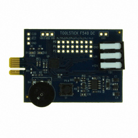
TOOLSTICK540DC
Description
DAUGHTER CARD TOOLSTICK F540
Manufacturer
Silicon Laboratories Inc
Series
ToolStickr
Type
MCUr
Datasheets
1.TOOLSTICK540DC.pdf
(274 pages)
2.TOOLSTICK540DC.pdf
(16 pages)
3.TOOLSTICK540DC.pdf
(12 pages)
Specifications of TOOLSTICK540DC
Contents
Daughter Card
Processor To Be Evaluated
C8051F54x
Processor Series
C8051F54x
Interface Type
USB
Operating Supply Voltage
2.7 V to 3.6 V
Lead Free Status / RoHS Status
Lead free / RoHS Compliant
For Use With/related Products
C8051F54x
For Use With
336-1345 - TOOLSTICK BASE ADAPTER336-1182 - ADAPTER USB DEBUG FOR C8051FXXX
Lead Free Status / Rohs Status
Lead free / RoHS Compliant
Other names
336-1717


C8051F54x
The TF3H bit is set when TMR3H overflows from 0xFF to 0x00; the TF3L bit is set when TMR3L overflows
from 0xFF to 0x00. When Timer 3 interrupts are enabled, an interrupt is generated each time TMR3H over-
flows. If Timer 3 interrupts are enabled and TF3LEN (TMR3CN.5) is set, an interrupt is generated each
time either TMR3L or TMR3H overflows. When TF3LEN is enabled, software must check the TF3H and
TF3L flags to determine the source of the Timer 3 interrupt. The TF3H and TF3L interrupt flags are not
cleared by hardware and must be manually cleared by software.
23.3.3. External Oscillator Capture Mode
Capture Mode allows the external oscillator to be measured against the system clock. Timer 3 can be
clocked from the system clock, or the system clock divided by 12, depending on the T3ML (CKCON.6),
and T3XCLK bits. When a capture event is generated, the contents of Timer 3 (TMR3H:TMR3L) are
loaded into the Timer 3 reload registers (TMR3RLH:TMR3RLL) and the TF3H flag is set. A capture event
is generated by the falling edge of the clock source being measured, which is the external oscillator/8. By
recording the difference between two successive timer capture values, the external oscillator frequency
can be determined with respect to the Timer 3 clock. The Timer 3 clock should be much faster than the
capture clock to achieve an accurate reading. Timer 3 should be in 16-bit auto-reload mode when using
Capture Mode.
If the SYSCLK is 24 MHz and the difference between two successive captures is 5861, then the external
clock frequency is as follows:
24 MHz/(5861/8) = 0.032754 MHz or 32.754 kHz
This mode allows software to determine the external oscillator frequency when an RC network or capacitor
is used to generate the clock source.
244
External Clock / 8
T3MH
SYSCLK / 12
0
0
1
T3XCLK
T3XCLK
X
0
1
0
1
SYSCLK/12
External Clock/8
SYSCLK
TMR3H Clock Source
SYSCLK
Figure 23.8. Timer 3 8-Bit Mode Block Diagram
0
1
1
0
M
H
T
3
M
T
3
L
CKCON
M
H
T
2
M
T
2
L
M
T
1
T
M
0
TR3
S
C
A
1
S
C
A
0
Rev. 1.1
TCLK
TCLK
TMR3RLH
TMR3RLL
TMR3H
TMR3L
T3ML
0
0
1
Reload
Reload
T3XCLK
X
0
1
To SMBus
To ADC,
TF3CEN
T3SPLIT
TF3LEN
T3XCLK
SMBus
TF3H
TF3L
TR3
SYSCLK/12
External Clock/8
SYSCLK
TMR3L Clock Source
Interrupt
Related parts for TOOLSTICK540DC
Image
Part Number
Description
Manufacturer
Datasheet
Request
R

Part Number:
Description:
KIT TOOL EVAL SYS IN A USB STICK
Manufacturer:
Silicon Laboratories Inc
Datasheet:

Part Number:
Description:
TOOLSTICK DEBUG ADAPTER
Manufacturer:
Silicon Laboratories Inc
Datasheet:

Part Number:
Description:
TOOLSTICK BASE ADAPTER
Manufacturer:
Silicon Laboratories Inc
Datasheet:

Part Number:
Description:
TOOLSTICK DAUGHTER CARD
Manufacturer:
Silicon Laboratories Inc
Datasheet:

Part Number:
Description:
TOOLSTICK DAUGHTER CARD
Manufacturer:
Silicon Laboratories Inc
Datasheet:

Part Number:
Description:
TOOLSTICK DAUGHTER CARD
Manufacturer:
Silicon Laboratories Inc
Datasheet:

Part Number:
Description:
TOOLSTICK PROGRAMMING ADAPTER
Manufacturer:
Silicon Laboratories Inc
Datasheet:

Part Number:
Description:
TOOLSTICK DAUGHTER CARD
Manufacturer:
Silicon Laboratories Inc
Datasheet:

Part Number:
Description:
KIT STARTER TOOLSTICK
Manufacturer:
Silicon Laboratories Inc
Datasheet:

Part Number:
Description:
KIT UNIVERSITY TOOLSTICK STARTER
Manufacturer:
Silicon Laboratories Inc
Datasheet:

Part Number:
Description:
DAUGHTER CARD TOOLSTICK F330
Manufacturer:
Silicon Laboratories Inc
Datasheet:

Part Number:
Description:
CARD DAUGHTER UNIVRSTY TOOLSTICK
Manufacturer:
Silicon Laboratories Inc
Datasheet:

Part Number:
Description:
DAUGHTER CARD TOOLSTICK F582
Manufacturer:
Silicon Laboratories Inc
Datasheet:

Part Number:
Description:
DAUGHTER CARD TOOLSTICK F500
Manufacturer:
Silicon Laboratories Inc
Datasheet:

Part Number:
Description:
DAUGHTER CARD TOOLSTICK F560
Manufacturer:
Silicon Laboratories Inc
Datasheet: